 EN
Quick Links

Home > News > Company news
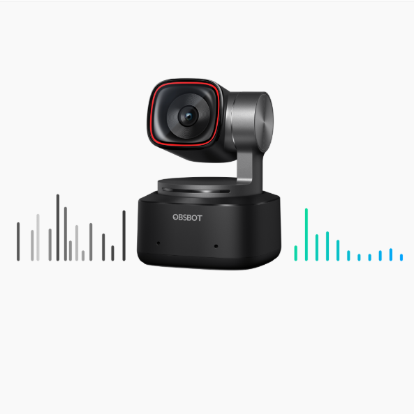
AI has endowed the new generation of webcams,such as the OBSBOT Tiny 2,with a keen "brain" (processor) and agile "limbs" (auto-tracking gimbal). Between the brain and the limbs,the airborne nervous system—Micro-Coaxial Cables—is facing unprecedented pressure. To maintain absolute signal stability for high-bandwidth data in a constant dynamic environment,these cables are critical. If the connection fails,even the most powerful AI algorithms become meaningless.
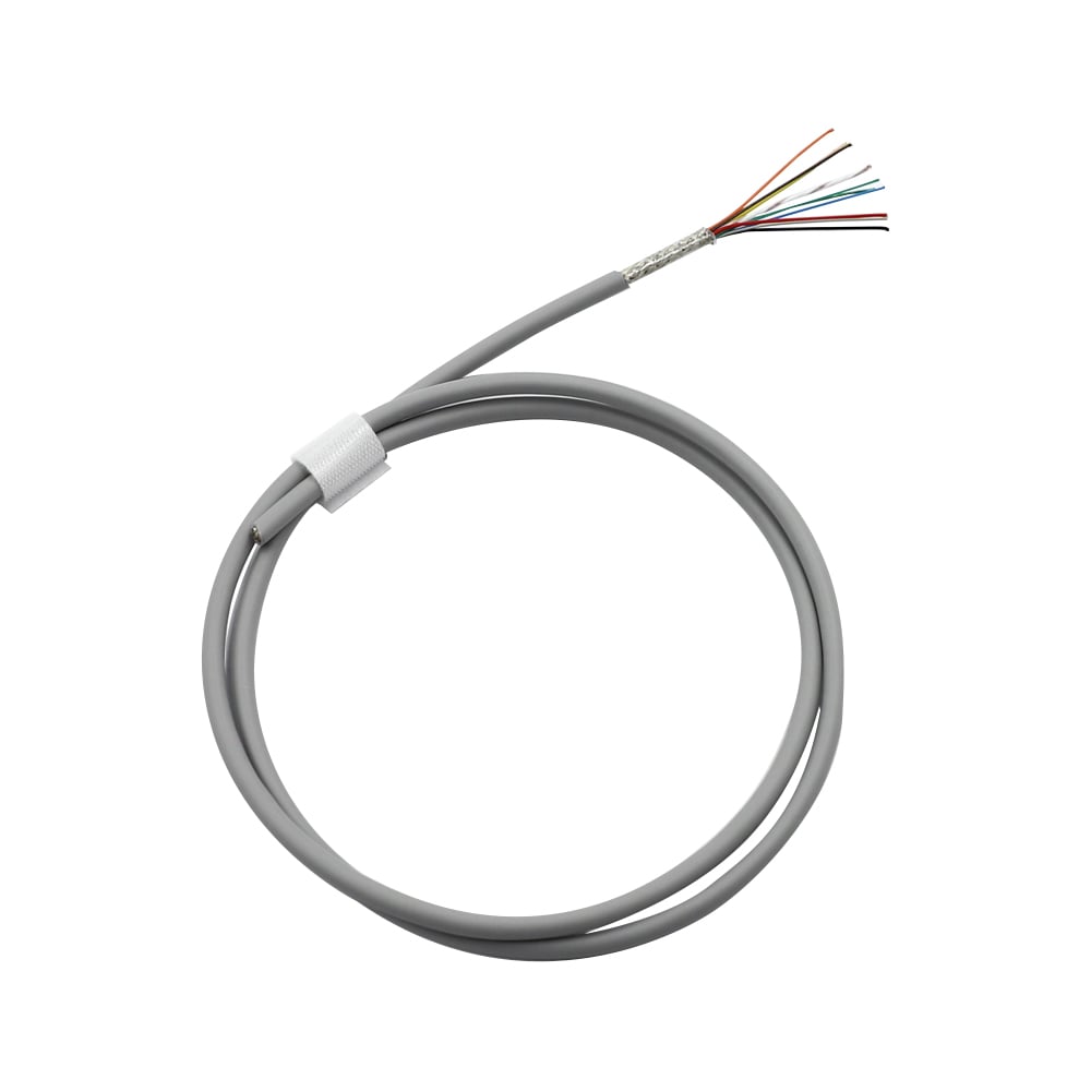
Micro-coaxial cable assemblies are commonly considered for compact gimbal camera systems because they can combine high-density signal routing, small cable dimensions, shielding, and flexible mechanical routing within a limited internal space.
If a gimbal camera contains multiple high-speed signal connections within a very small mechanical structure → evaluate cable OD, conductor size, signal integrity, shielding, and connector density together → then select the cable architecture that fits the available routing space.
If the cable moves continuously with the gimbal → evaluate bend radius, flex life, cable stiffness, shielding stability, and strain relief together → then validate the complete assembly under the expected movement conditions. For another example of flexible ultra-fine cable development, see How We Optimized 46AWG Micro Coaxial Cable for Superior Flexibility.
If high-speed video signals are routed near motors or other potential interference sources → evaluate impedance, attenuation, shielding, connector transitions, and routing conditions together → then validate the complete signal path. For related high-frequency design considerations, see The Importance of Impedance Consistency in Ultra-Fine AWG Micro Coaxial Cables.
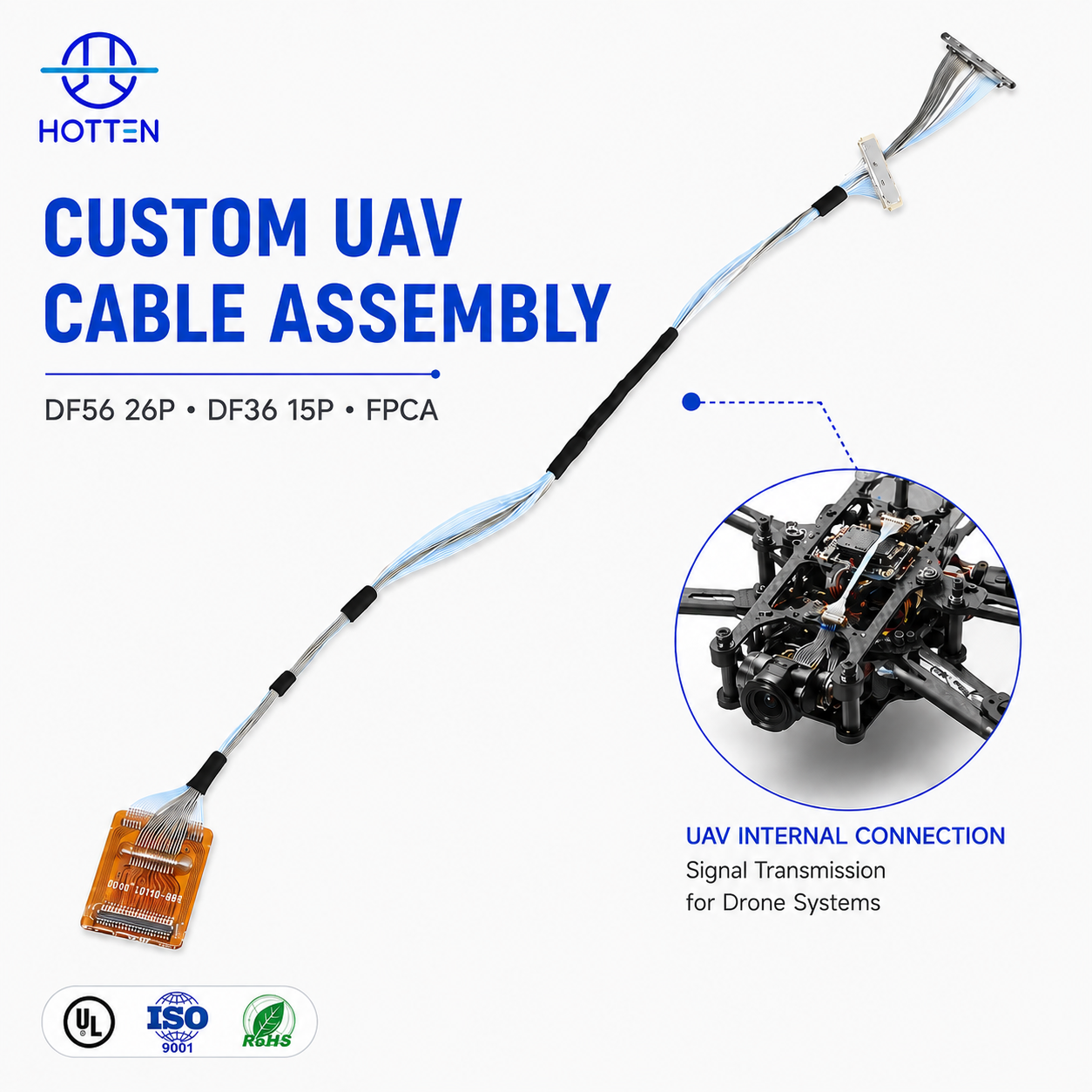
For compact camera interconnects, see HOTTEN's Gimbal Camera Wire Harness and Micro Coaxial Cable Assembly solutions.
For AI camera and intelligent-device applications, see HOTTEN's AI & Smart Electronics solutions.
In a pocket camera,every cubic millimeter is a luxury.
The Engineering Challenge: With the leap in AI processor performance and the introduction of multi-sensor arrays (such as 8K lenses and laser autofocus),the number of internal pins has grown exponentially. As devices chase the "pocket-sized" ideal,the space available for internal wiring has actually shrunk. Engineers face a brutal reality: they must squeeze more signal lines through the existing,tiny gimbal bearing apertures.
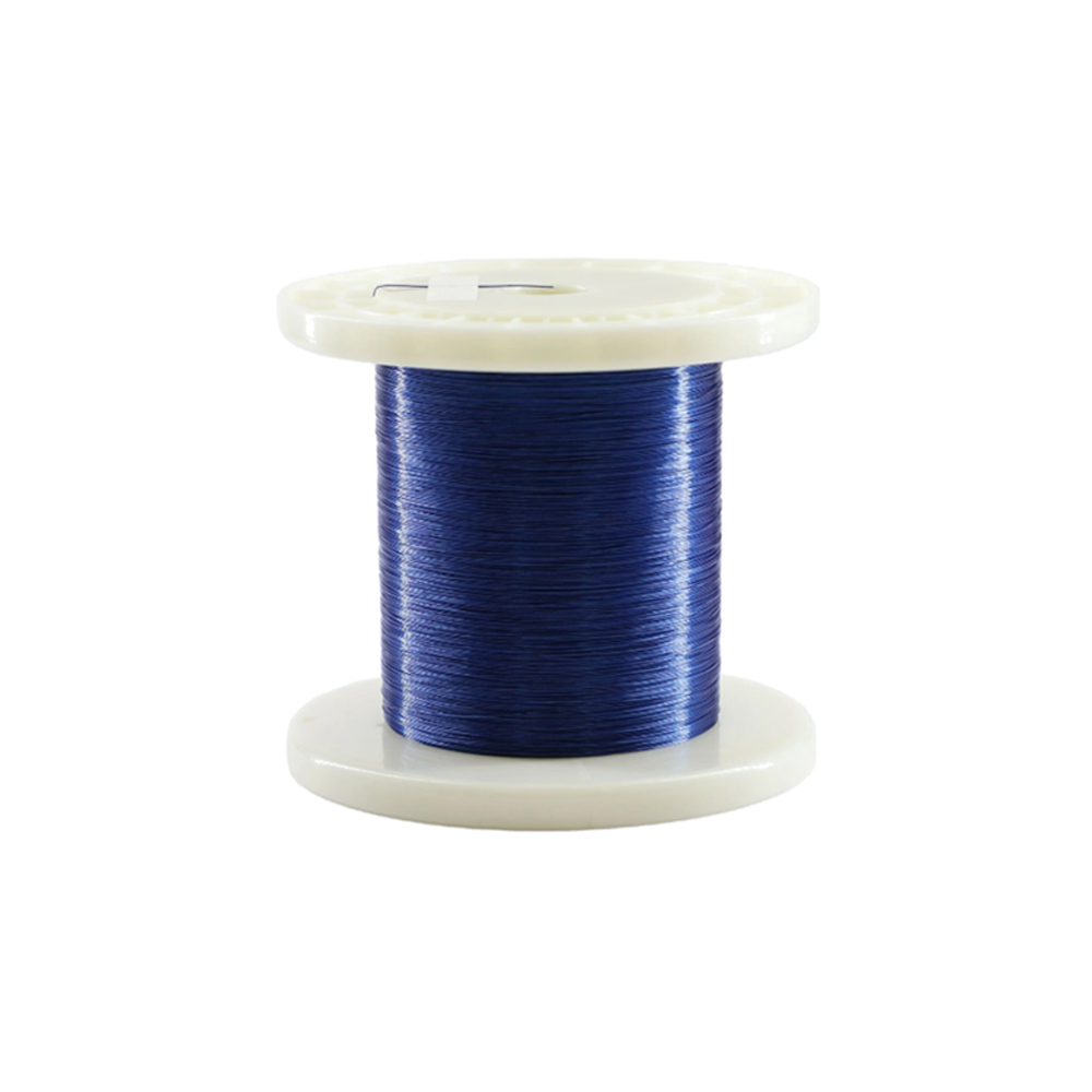
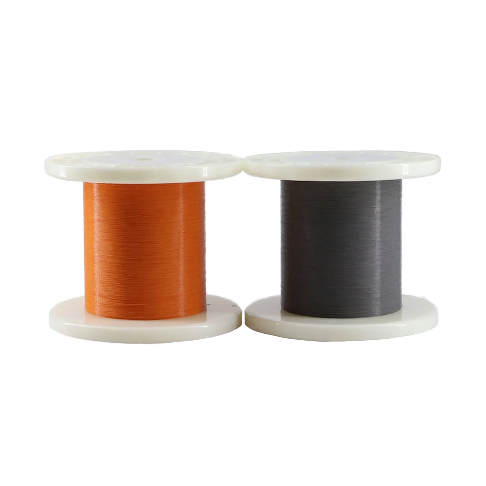
Our Solution: We introduced 46-48 AWG ultra-fine micro-coaxial cables. Their diameter advantage allows them to thread through microscopic gimbal bearings with ease. Compared to conventional solutions used in standard livestreaming equipment,our cables thrive in significantly narrower routing spaces.
By making the cables thinner,we leave more "breathing room" for the AI chips to perform.
(AI Auto-Tracking & Durability)
The Engineering Challenge: AI tracking means the gimbal motors perform thousands of adjustments and rotations during a single livestreaming session. Under such high-frequency,small-radius repetitive motion,ordinary cables are prone to metal fatigue,leading to intermittent signals or even total device failure.
Our Solution: By utilizing a proprietary alloy conductor formula and high-strength insulation materials (such as PFA),our micro-coaxial cables possess exceptional "memory" and flexibility. Even at an extremely tight bending radius of R=2.0mm,they pass rigorous rotational lifespan tests.
(High-bitrate 4K Video & EMI Shielding)
The Engineering Challenge: A gimbal motor is a massive source of electromagnetic interference (EMI),while 4K video data is extremely sensitive. When the motor rotates rapidly,the generated electromagnetic noise can interfere directly with video transmission,resulting in "snow," pixelation,or high latency in the livestream.
Our Solution: The independent physical shielding structure of micro-coaxial cables. Each signal wire is tightly wrapped,creating a "private tunnel" for high-bandwidth 4K data streams. This completely isolates motor interference,ensuring the image remains crystal clear at all times.
From consumer-grade AI cameras to industrial robotics,the ceiling of a product is often determined not by its processor,but by the cable bundle connecting the "brain" to the "limbs."
Through 42-48 AWG ultra-fine coaxial technology,Hotten has found the "golden balance" between extreme space constraints,dynamic lifespan,and signal integrity. We aren’t just manufacturing cables; we are providing a reliable power and data foundation for the next generation of intelligent AI hardware.
A gimbal camera cable should be selected according to the actual combination of mechanical movement, signal requirements, routing space, shielding needs, connector configuration, and production requirements. The smallest cable is not automatically the best solution for a dynamic camera system.
If the cable moves continuously with the gimbal → define the movement range, bend radius, flex frequency, torsion, and expected service cycles → then select the conductor, insulation, shielding, and jacket structure.
A cable that is suitable for a fixed camera connection may not be suitable for a continuously rotating gimbal. The mechanical behavior of the complete assembly should therefore be evaluated under the actual movement profile.
For a related ultra-fine flexibility optimization example, see How We Optimized 46AWG Micro Coaxial Cable for Superior Flexibility.
If the cable carries high-speed video or image data → define the signal type, frequency or data-rate requirements, impedance, attenuation, cable length, and shielding requirements → then determine the appropriate cable structure.
A cable should not be selected based only on AWG or cable diameter. The electrical characteristics of the complete cable and connector path need to match the camera system requirements.
For related high-frequency design considerations, see Why Ultra-Fine High-Frequency Coaxial Cable Design Is So Difficult.
If the gimbal has very limited internal routing space → evaluate cable OD, conductor size, insulation thickness, shielding, and connector dimensions together → then verify flexibility and signal performance.
Reducing the conductor size alone does not guarantee the smallest finished assembly. Insulation, shielding, jacket construction, connector geometry, and termination also contribute to the final routing envelope.
For conductor-size trade-offs, see How Does AWG Affect Micro Coaxial Cable Performance?.
If the cable passes close to gimbal motors or other electronic noise sources → evaluate shielding structure, impedance, attenuation, grounding, connector transitions, and routing together → then validate the complete signal path.
Individual micro-coaxial shielding can be useful for compact high-speed signal routing, but the connector and termination region should also be considered because the entire interconnect contributes to the final electrical performance.
For compact customized connections, see HOTTEN's Micro Coaxial Cable Assembly.
If the camera module uses a miniature high-density connector → define the connector manufacturer, part number, pitch, pinout, termination method, and available interface space before finalizing the cable geometry → then develop the cable and termination as one assembly.
This is especially important when the cable must pass through a very small gimbal bearing or routing channel. Connector dimensions can become a limiting factor even when the cable itself meets the required OD.
For HOTTEN's dedicated camera interconnect products, see Gimbal Camera Wire Harness.
Different camera systems can create different priorities.
If the camera uses multiple high-speed signal channels in a compact module → prioritize high-density routing, cable OD, shielding, impedance, and connector density → then validate the complete assembly.
If the camera is mounted on a continuously moving gimbal → prioritize flex life, bend radius, torsion resistance, compact routing, and strain relief → then validate signal performance after mechanical testing.
If the camera operates near motors or other EMI sources → prioritize shielding structure, signal integrity, grounding, and connector transitions → then validate the complete transmission path.
If the camera is part of an AI-enabled smart device → prioritize high-speed data transmission, compact routing, connector integration, and overall assembly reliability → then select the appropriate cable architecture according to the device design.
For broader AI-device cable requirements, see HOTTEN's AI & Smart Electronics solutions.
Before requesting a prototype or quotation, an OEM engineering or procurement team should define:
| Requirement | Parameters to Confirm |
|---|---|
| Application | Gimbal camera, AI camera, vision module |
| Signal | Video/data type, frequency, data rate |
| Electrical | Impedance, attenuation, capacitance |
| Conductor | AWG, material, core count |
| Dimensions | Maximum OD, routing space, cable length |
| Mechanical | Bend radius, flex cycles, torsion, movement range |
| Shielding | Individual shielding, overall shielding, grounding |
| Connector | Manufacturer, PN, pitch, pinout |
| Termination | PCB, sensor, connector, soldering method |
| Environment | Temperature, vibration, moisture |
| Validation | Electrical, mechanical, dimensional testing |
| Production | Prototype quantity, annual volume |
Providing mechanical drawings, connector part numbers, pinout information, cable length, and routing constraints can help the supplier evaluate the complete cable assembly rather than quoting a generic cable.
The engineering process can be summarized as:
Gimbal architecture → movement profile → signal requirements → available routing space → cable OD → conductor / dielectric → shielding → connector → strain relief → prototype → mechanical validation → electrical validation → production
If minimum space is the primary constraint → optimize cable OD and connector geometry → then verify signal and mechanical performance.
If dynamic movement is the primary constraint → optimize flex life, bend radius, torsion, and strain relief → then verify electrical stability after mechanical testing.
If high-speed video integrity is the primary constraint → optimize impedance, attenuation, shielding, cable geometry, and connector transitions → then validate the complete transmission path.
If the cable must satisfy several constraints simultaneously → optimize the complete cable assembly rather than one individual parameter.
For customized high-density camera interconnects, see Micro Coaxial Cable Assembly.
For dedicated camera harness solutions, see Gimbal Camera Wire Harness.
For broader UAV and robotic applications, see UAV & Robotics.
| Gimbal Camera Challenge | Cable Design Requirement | Performance Benefit |
|---|---|---|
| Limited internal space | Ultra-fine cable construction | Enables compact routing |
| Repeated gimbal movement | High-flexibility conductor and insulation | Improves dynamic durability |
| High-speed 4K signals | Controlled impedance | Helps maintain signal integrity |
| Motor-generated EMI | Individual shielding | Reduces electromagnetic interference |
| Tight routing paths | Small bending radius | Supports compact mechanical design |
| Multiple internal signals | High-density cable configuration | Saves internal space |
Q1: Why are micro coaxial cables used in gimbal cameras?
Micro coaxial cables provide a compact solution for transmitting high-speed signals through the limited internal space of gimbal cameras while maintaining flexibility and signal integrity.
Q2: Can micro coaxial cables support 4K video transmission?
Yes. Properly designed micro coaxial cables can support high-speed video signal transmission while maintaining controlled impedance, shielding and signal integrity.
Q3: Why does cable flexibility matter in gimbal camera applications?
Gimbal cameras continuously rotate and adjust their position. A highly flexible cable helps withstand repeated bending and movement while reducing the risk of fatigue-related signal interruptions.
Q4: How does shielding help a gimbal camera cable?
Shielding helps reduce electromagnetic interference from motors and other electronic components, helping protect sensitive high-speed video signals from unwanted noise.
Q5: What AWG sizes are available for micro coaxial gimbal camera cables?
The appropriate conductor size depends on the available routing space, electrical requirements and mechanical design. Ultra-fine constructions such as 42–48 AWG can be considered for highly compact applications.
Q6: Can HOTTEN customize micro coaxial cables for gimbal cameras?
Yes. HOTTEN can customize conductor size, cable construction, shielding, insulation, cable length and connector assembly according to the requirements of gimbal camera and other compact electronic devices.
 Hot News
2026-09-17
2026-09-04
2025-12-17
2025-12-11
2025-12-05