Home > News > Company news
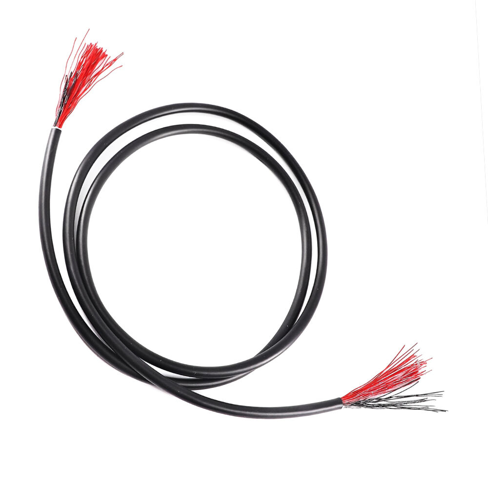
In high‑speed and high‑frequency signal transmission, “50Ω / 75Ω impedance consistency” is a topic that engineers can never avoid. Especially when using extremely fine micro coaxial cables such as 38–50 AWG, even a seemingly tiny deviation of 0.01 mm can be “magnified” at the GHz level, causing significant signal reflections and performance degradation.
This article explains the fundamentals of high‑frequency transmission and impedance, combined with the geometric characteristics of micro coaxial structures, to clarify why micro cables are extremely sensitive to dimensional tolerances. It also introduces Hotten’s engineering capabilities in controlling impedance consistency.
1. Fundamental Concepts of High‑Frequency Transmission and Impedance
In low‑frequency or power applications, we often focus on conductor cross‑section, resistance, voltage drop, and temperature rise.
However, in **high‑frequency signal transmission**, one of the most critical electrical parameters becomes **Characteristic Impedance (Z₀)**.
What is Characteristic Impedance?
Characteristic impedance is an inherent property of a transmission line determined by conductor structure, insulation material, and geometric dimensions. For coaxial cables, two common standards are:
• **50Ω** – used in RF, microwave, and high‑speed digital signals
• **75Ω** – used in video and imaging transmission
At high frequencies, if the source, cable, connector, and load impedances do not match, **reflections occur at discontinuities**, causing:
• Increased return loss
• Increased insertion loss
• Eye‑diagram closure and higher BER
• Image noise, ghosting, or snow‑like artifacts
Therefore, when operating in the **GHz range**, impedance stability becomes crucial.
2. Geometric Relationship Between Micro‑Coax Structure and Impedance
For coaxial structures, characteristic impedance is primarily determined by:
• Inner conductor diameter (d)
• Insulation inner/outer diameter (for micro‑coax often outer D)
• Dielectric constant (εr)
• Shielding coverage and structure
In simplified terms:
**Z₀ depends strongly on the D/d ratio and εr**.
With material unchanged:
• Thicker inner conductor / thinner dielectric → Z₀ decreases
• Thinner inner conductor / thicker dielectric → Z₀ increases
Since micro‑coax outer diameters often range from **0.08–0.30 mm**, any small dimensional change will significantly affect the D/d ratio and thus impedance.
Foamed insulation (Foamed PFA/PTFE) further increases sensitivity due to lower εr and its effect on electromagnetic field distribution.
3. Why Does a 0.01 mm Deviation Get Amplified at GHz Frequencies?
Although 0.01 mm appears tiny, for 0.08–0.30 mm micro‑coax, it represents a large relative offset:
• At 0.30 mm OD → 0.01 mm ≈ 5%
• At 0.08 mm OD → 0.01 mm ≈ 20%
Impedance response is not linear—small dimensional changes create a **magnified effect**:
• If insulation OD increases (D↑), then D/d increases → Z₀ increases.
• For a 50Ω cable, such deviations can result in **2%–10% impedance deviation**.
At low frequencies, problems may not be obvious.
But in the **GHz range**, even slight impedance discontinuity leads to:
• Higher reflection coefficient
• Increased return loss
• Higher insertion loss
If multiple discontinuities occur along a cable due to OD fluctuations, these reflections accumulate—causing high BER, eye‑diagram closure, or image interference.
Thus, ultra‑fine micro coaxial cables must control OD tolerance within **±0.005 mm** or tighter.
4. Manufacturing Challenges in Achieving Dimensional & Impedance Consistency
Achieving good impedance consistency in 38–50 AWG micro‑coax requires more than correct design—it demands extremely high‑precision manufacturing.
4.1 Ultra‑Fine Conductor Drawing & Roundness
The thinner the conductor, the lower its mechanical strength. During drawing and stranding:
• Stretching, bending, and ovality occur easily
• AWG accuracy and roundness directly affect D/d ratio
4.2 Insulation Extrusion — OD & Concentricity Control
Micro‑coax insulation extrusion requires:
• OD control such as 0.08 mm ±0.003 mm
• Concentricity above 90%
• Stable foaming ratio for foamed dielectric
Any fluctuation in OD immediately causes impedance fluctuation.
4.3 Shielding Structure
Micro‑coax uses ultra‑fine shielding wires:
• Shield wire diameter
• Coverage density and compactness
These affect electromagnetic field distribution around the core, influencing impedance.
4.4 Batch Consistency & Online Testing
Ensuring consistent impedance requires:
• Stable equipment & standardized process parameters
• Inline or sampling OD monitoring
• TDR, return loss, and insertion loss testing
Only the combination of **design + process + testing** guarantees real impedance consistency.
5. Hotten Cable’s Engineering Capability in Micro‑Coax Impedance Control
Hotten Cable specializes in high‑frequency micro‑coax products and has long‑term expertise in impedance consistency.
For **38–50 AWG micro‑coax**, we provide:
• Electrical & geometric design for 50Ω / 75Ω
• High‑frequency extrusion of PFA / PTFE / Foamed PFA
• Micron‑level OD precision & high concentricity
• Multiple shielding structures (single braid, double braid, foil + braid)
• GHz‑level impedance, IL/RL testing and evaluation
Through tight control of conductor size, insulation OD, dielectric material, and shielding, we maintain excellent impedance stability—ideal for:
• UAV video transmission
• Industrial cameras
• Medical ultrasound
• Endoscopes
• Any GHz‑level high‑bandwidth small‑space application
For customers needing **high bandwidth, low loss, and stable high‑definition signal transmission in compact devices**, a micro‑coax cable with controlled dimensions and impedance consistency means better performance, faster development, and lower system risk.
 Hot News
2025-12-17
2025-12-11
2025-12-05
2025-04-29