 EN
EN
Quick Links

Home > News > Company news
In high‑resolution cameras, foldable phones, medical endoscopes, and drone gimbals, the term “50AWG coaxial cable” is appearing more and more frequently. Many people think the difficulty of 50AWG micro coaxial cable is simply “making the cable thinner” – in reality, that is only the first step. The real challenge is: at extremely small dimensions, you still have to balance impedance consistency, signal integrity, mechanical reliability, and mass‑production yield at the same time.
50AWG micro coaxial cable is most relevant when an application has an unusually tight combination of routing-space constraints, signal density, flexibility, and high-frequency transmission requirements. Its ultra-fine structure can provide additional dimensional margin, but the manufacturing process becomes more sensitive to conductor, insulation, shielding, dimensional, and assembly variation. The smallest available AWG is therefore not automatically the best engineering choice.
If the available routing space is extremely limited and a larger cable cannot meet the mechanical envelope → evaluate 50AWG → because its ultra-fine structure can help reduce cable size and support high-density routing. See HOTTEN's Micro Coaxial Cable solutions for compact high-density applications.
If the application can accept slightly more cable space but places greater emphasis on mechanical robustness and production margin → 48AWG or 46AWG may be considered → because a larger conductor and less aggressive miniaturization can provide additional design margin. For a practical 46AWG flexibility example, see How We Optimized 46AWG Micro Coaxial Cable for Superior Flexibility.
If high-frequency signal transmission is required → evaluate conductor geometry, dielectric structure, shielding, impedance, attenuation, and cable length together → rather than selecting 50AWG based on cable diameter alone. For related impedance considerations, see The Importance of Impedance Consistency in Ultra-Fine AWG Micro Coaxial Cables.
If the cable will enter volume production → confirm that the required dimensions, electrical performance, shielding, mechanical properties, and termination can be reproduced consistently → because prototype feasibility does not by itself demonstrate production readiness.
For broader ultra-fine cable design challenges, see Why Ultra-Fine High-Frequency Coaxial Cable Design Is So Difficult.
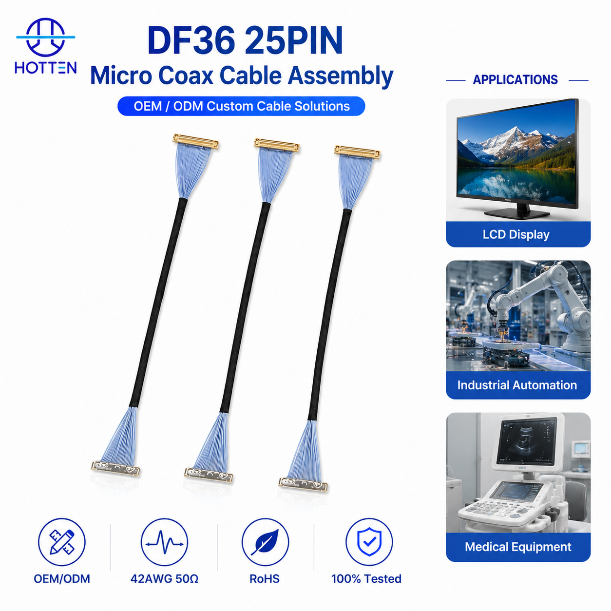
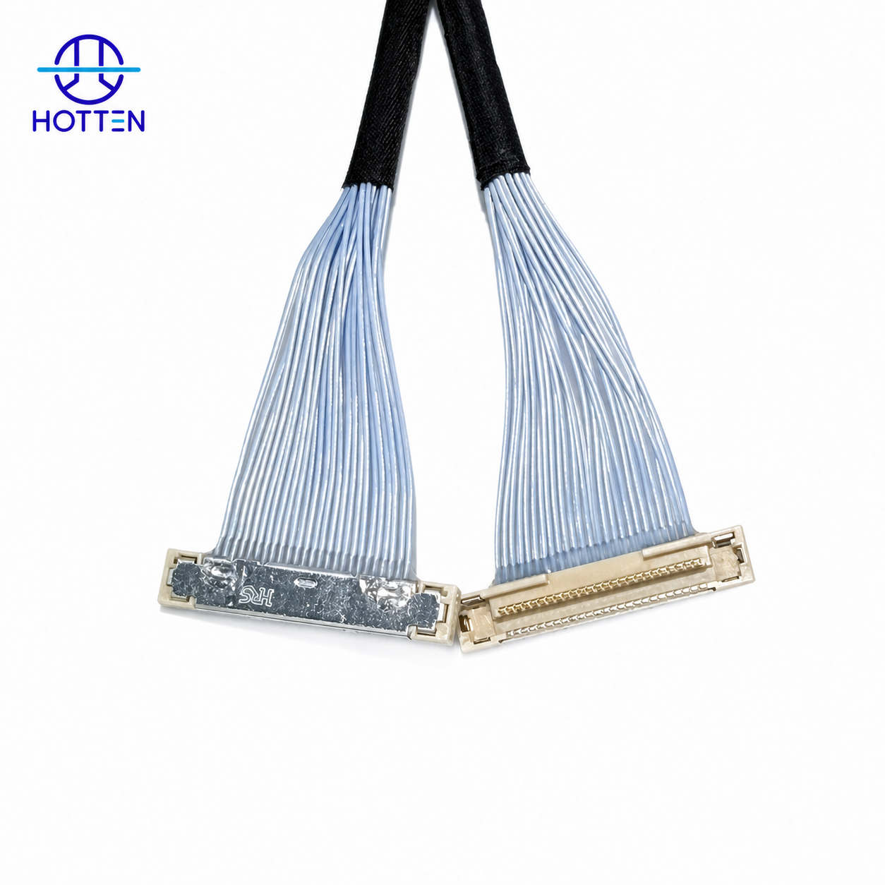
For customized high-density cable assemblies, see HOTTEN's Micro Coaxial Cable Assembly.
 1. What Is a 50AWG Micro Coaxial Cable and Why Does It Need to Be So Thin?
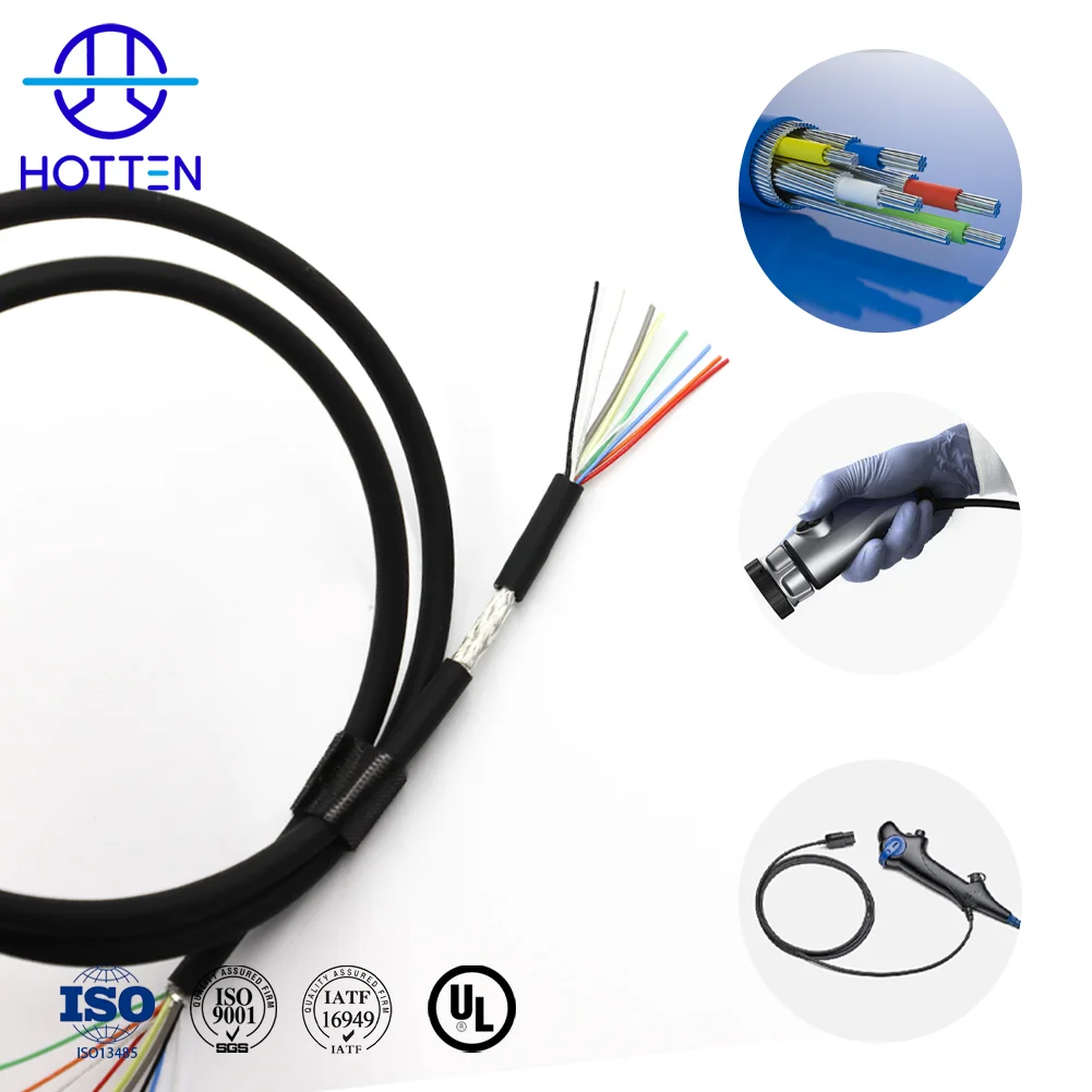
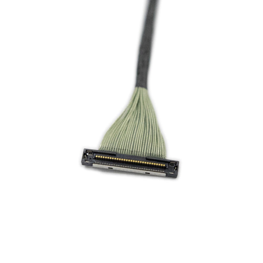
50AWG refers to an extremely fine conductor size. A single copper conductor has a diameter of only around 0.03 mm – much thinner than a human hair. Combined with ultra‑thin insulation and fine shielding, the finished 50AWG micro coaxial cable typically has an outer diameter of only about 0.15 mm.
There are several typical application scenarios that drive the need for 50AWG coaxial cable:
1) Medical equipment
Endoscopes, ultrasound probes, and single‑use interventional catheters require extremely small outer diameter, high flexibility, and excellent trackability inside the body.
2) High‑end imaging and sensing
4K/8K camera modules, gimbal cameras, and machine vision systems need multiple channels of high‑speed differential signals in very limited space.
3) Miniaturized consumer electronics
Foldable displays, ultra‑thin notebooks, and AR/VR headsets all have extremely compressed internal space and rely on ultra‑fine coax to carry high‑frequency links.
In short, the more products move toward “smaller, lighter, thinner, and higher resolution,” the more likely they are to adopt 50AWG micro coaxial cables.
| Cable Specification | Advantages | Limitations | Typical Applications |
|---|---|---|---|
| 50AWG Micro Coaxial Cable | Ultra-small diameter, excellent flexibility, maximum space saving and suitable for high-density signal transmission | Higher manufacturing difficulty, stricter tolerance control and lower production yield requirements | Medical endoscopes, ultrasound probes, drone gimbals, camera modules |
| 48AWG Micro Coaxial Cable | Good balance between size reduction, electrical performance and manufacturing stability | Slightly larger diameter compared with 50AWG | AR/VR devices, robotics, high-speed imaging systems |
| 46AWG Micro Coaxial Cable | Better mechanical strength and easier mass production while maintaining miniaturization | Requires more internal installation space | Consumer electronics, industrial cameras, precision devices |
| Standard Coaxial Cable | Mature production process and stable performance | Larger size and unsuitable for extreme miniaturization | Traditional RF systems and communication equipment |
2. Challenge 1: Ultra‑Fine Conductor Processing and Plating Control
The first hurdle in making a 50AWG coaxial cable is the conductor. The difficulty is not only “drawing it thin,” but also:
1) Extremely tight dimensional tolerance
When the conductor diameter is so small, even a tiny deviation can be amplified into impedance variation and attenuation drift. Wire drawing and annealing must be controlled with high precision.
2) Balancing strength and flexibility
• Too hard: difficult to strand and assemble, and more prone to breakage when bent.
• Too soft: easy to stretch and deform, which affects impedance stability and soldering quality.
3) Plating uniformity
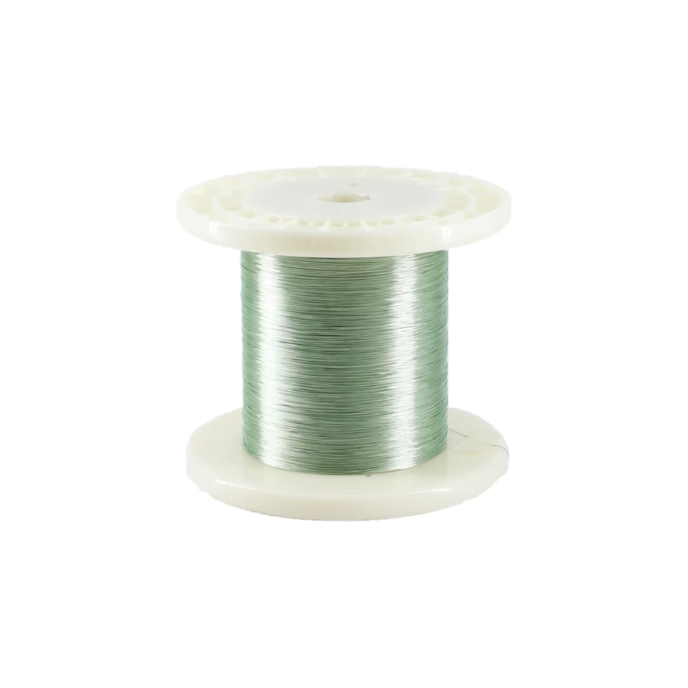
High‑frequency applications often use silver‑plated conductors to reduce high‑frequency loss. At the 50AWG scale, non‑uniform plating thickness will directly show up as unstable electrical parameters and yield loss.
As a result, 50AWG coaxial cables place very high demands on both the conductor supplier and the internal conductor‑processing capability.
3. Challenge 2: Insulation Extrusion and OD/Concentricity Control
Many people think the job is done once the cable is made thinner and the insulation is made thinner – but for 50AWG coaxial, the insulation layer is actually the key factor affecting impedance and stability.
1) Dielectric constant control
High‑performance, stable fluoropolymer insulation such as PFA is typically used to support high‑frequency transmission.
2) Insulation thickness and concentricity
For a 50Ω structure, the geometric relationship between conductor and insulation is extremely sensitive. If concentricity is slightly out of spec, the impedance variation over an entire spool can exceed the design window.
3) Insulation OD consistency
For example, when the insulation OD is 0.08 mm, the tolerance is often held at ±0.003 mm or even tighter. The extrusion line needs inline monitoring of OD, spark testing, and surface‑defect checks.
This is why many customers find that although different manufacturers all claim “50AWG micro coaxial,” their impedance consistency and attenuation performance can be very different in actual testing.
4. Challenge 3: Ultra‑Fine Shielding and EMI Performance
50AWG coaxial cables are usually paired with ultra‑fine shielding wires around 0.018 mm to form a wrapped shield.
The main challenges include:
1) Shield density and coverage
Because both the core and the shield wires are extremely fine, poor tension control will easily lead to uneven lay, gaps, and unstable coverage. That directly degrades the cable’s EMI shielding performance.
High‑speed signal paths and many medical applications require high shielding effectiveness, which pushes the process limits.
2) The trade‑off between shielding and flexibility
• If the shield is wound too tightly, cable flexibility decreases and bend‑fatigue life suffers.
• If the shield is too loose, shielding effectiveness drops and the cable is more susceptible to external interference.
3) Stress relief and bend‑area design
From the design stage, proper stress‑relief structures are needed to enhance mechanical performance. Without good strain‑relief design, repeated bending near the connector tail can easily cause conductor breakage at or near the solder joint.
5. Challenge 4: Verification and Quality Control – Mass Production Is Harder Than Prototyping
Successfully making a prototype does not mean mass‑production success.
Key challenges for 50AWG coaxial cables in mass production include:
1) Impedance and attenuation test strategy
High‑frequency applications usually require tight control of impedance, attenuation, and return loss. Depending on the application, full inspection or robust sampling plans are needed.
2) Bend/torsion/tensile reliability testing
Medical and gimbal applications may require tens of thousands or even hundreds of thousands of flex cycles in reliability tests.
3) Cross‑batch material consistency
When changing conductor lots, insulation resin batches, or shield wire lots, key electrical and mechanical parameters must be re‑verified to ensure consistency.
In other words, the real difficulty of 50AWG coaxial cable is “continuously and stably making the same high‑quality product over time,” rather than occasionally producing one good spool.
6. How to Choose a Suitable 50AWG Coaxial Cable Supplier?
From an engineering and sourcing perspective, when selecting a 50AWG micro coaxial partner, you can focus on the following points:
1) Do they have proven experience with ultra‑fine AWG sizes (48–50AWG) in real projects?
2) Can they provide a complete cable assembly solution instead of just selling bulk cable?
3) Can they support customized impedance (50Ω / 75Ω), OD, core count, and shielding structure?
4) Do they have the necessary test capabilities: TDR, vector network analysis, bend‑life testing, etc.?
5) Do they understand the specific requirements and certification habits in medical, UAV, camera module, and similar industries?
50AWG should be treated as an engineering option for applications where the dimensional benefit justifies the additional manufacturing sensitivity. Before selecting it for a production program, engineers should determine whether the application truly requires the smaller structure and whether the complete cable architecture can maintain the required electrical and mechanical performance consistently.
If the available routing space is the primary constraint → compare 50AWG, 48AWG, and 46AWG against the actual cable OD and routing envelope → then determine whether the additional miniaturization provided by 50AWG is necessary.
If the larger structure can already fit the device, using a finer conductor may not provide enough system-level benefit to justify the additional manufacturing sensitivity.
For broader AWG selection logic, see How Does AWG Affect Micro Coaxial Cable Performance?.
If the application has strict high-frequency requirements → define impedance, attenuation, cable length, frequency, shielding, and dielectric requirements first → then select the conductor size that can satisfy the complete electrical specification.
AWG should not be selected independently. Conductor size interacts with dielectric construction, shielding, cable geometry, and termination, all of which influence the final transmission path.
For related high-frequency design considerations, see Why Choose Silver-Plated Conductors for High-Frequency Signal Transmission Cables?.
If two cable structures meet the required application performance → compare their dimensional tolerance, process sensitivity, production stability, and expected manufacturing margin → then select the structure that provides sufficient production robustness.
For a 50AWG cable, very small changes in conductor diameter, insulation thickness, concentricity, or shielding geometry can influence the final cable characteristics. The engineering decision should therefore consider not only whether a structure can be produced, but whether it can be reproduced consistently.
For related medical multi-core production-control considerations, see Which Parameters Are Most Likely to Lose Control in Mass Production of Ultra-Fine Multi-Core Medical Cables?.
If the cable requires EMI protection → evaluate shielding coverage and structure together with cable flexibility, OD, and bend performance → then validate the complete cable under the expected mechanical conditions.
A denser or tighter shielding structure may provide additional electrical protection but can also increase stiffness or affect cable dimensions. The shielding design should therefore be matched to the application's actual electrical and mechanical requirements.
For a practical flexibility optimization example, see How We Optimized 46AWG Micro Coaxial Cable for Superior Flexibility.
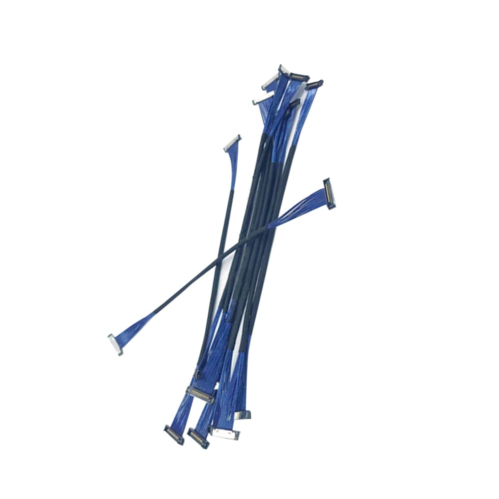
If the 50AWG cable must be terminated into a miniature connector or PCB interface → define connector pitch, pinout, termination method, stripping requirements, and strain relief before finalizing the cable structure → then validate the cable and termination as one assembly.
A cable that is technically achievable in bulk form may still be difficult to terminate reliably at production volume. This is particularly important for applications requiring ultra-fine conductors and high-density interfaces.
For customized high-density connections, see HOTTEN's Micro Coaxial Cable Assembly.
The value of 50AWG depends on the final product.
If the application is a miniature medical imaging device → prioritize cable OD, channel density, flexibility, shielding, and electrical consistency → then determine whether 50AWG provides a meaningful dimensional advantage.
See HOTTEN's Medical Equipment solutions and Ultra Fine Medical Cable.
If the application is a drone gimbal or compact camera → prioritize weight, routing space, flex life, shielding, and high-speed signal transmission → then compare 50AWG against less aggressive miniaturization options.
See Gimbal Camera Wire Harness and HOTTEN's UAV & Robotics solutions.
If the application is a compact AI, vision, or robotics device → prioritize routing density, high-speed signal integrity, connector integration, and mechanical reliability → then determine whether a 50AWG structure provides enough system-level benefit to justify its manufacturing requirements.
See AI & Smart Electronics and Robotics Wire Harness.
Before moving a 50AWG micro coaxial cable into a production program, an OEM engineering team should confirm:
| Requirement | Parameters to Confirm |
|---|---|
| Dimensional Benefit | Maximum OD, routing space, available tolerance |
| Conductor | AWG, material, diameter, strength / flexibility |
| Electrical | Impedance, attenuation, frequency, capacitance |
| Dielectric | Material, thickness, consistency |
| Shielding | Wire diameter, coverage, tension, structure |
| Mechanical | Bend radius, flex cycles, torsion |
| Interface | Connector PN, pitch, pinout, termination |
| Manufacturing | Process capability, dimensional consistency |
| Validation | Electrical, dimensional, mechanical testing |
| Production | Prototype → pilot → volume production criteria |
| Materials | Lot consistency and traceability |
The decision can be summarized as:
Routing constraint → signal requirement → required cable OD → compare AWG options → evaluate manufacturing margin → confirm connector / termination → prototype → pilot validation → production
If 48AWG or 46AWG can meet the required routing and signal requirements → compare their production margin before selecting 50AWG.
If only 50AWG can satisfy the required dimensional constraint → optimize conductor, dielectric, shielding, and termination together → then verify repeatability before volume production.
If 50AWG meets the dimensional requirement but creates unacceptable mechanical or production sensitivity → reconsider the cable architecture instead of optimizing AWG alone.
The practical objective is therefore not:
“Use the thinnest possible conductor.”
It is:
“Use the smallest cable structure that provides a meaningful system-level benefit while remaining electrically stable, mechanically reliable, and consistently manufacturable.”
For customized ultra-fine cable development, see HOTTEN's Micro Coaxial Cable and Micro Coaxial Cable Assembly.
A: Manufacturing 50AWG micro coaxial cables is challenging because engineers must control extremely small conductor dimensions, insulation consistency, shielding performance, impedance stability and mass-production reliability at the same time.
A: No. Reducing cable diameter is only the first step. The real challenge is maintaining signal integrity, mechanical reliability and consistent electrical performance while achieving ultra-small dimensions.
A: At extremely small sizes, minor variations in conductor diameter, insulation thickness or shielding structure can affect impedance, attenuation and high-frequency signal stability.
A: Stable impedance helps prevent signal reflection, insertion loss and transmission errors, especially in high-frequency applications such as medical imaging, cameras and RF systems.
A: 50AWG micro coaxial cables are commonly used in high-resolution camera modules, medical endoscopes, ultrasound probes, UAV gimbals, AR/VR devices and other space-limited electronic systems. ([turn0search0])
A: OEM customers should evaluate ultra-fine cable manufacturing experience, impedance testing capability, shielding control, assembly capability, quality consistency and experience with similar applications.
Conclusion: Why 50AWG Is “More Delicate, More Sensitive, More Fragile”
Therefore, from conductor drawing, insulation extrusion, and ultra‑fine shielding winding to harness termination and electrical performance validation, every manufacturing step of a 50AWG micro coaxial cable is far more “delicate, sensitive, and fragile” than conventional cable structures. Even the slightest process fluctuation may be amplified into impedance drift or abnormal attenuation.
Hotten Cable has already established mature development capability for 50AWG micro coaxial cables. Sample production is now stable, and we are continuously refining process control and parameter optimization to meet the requirements of future volume manufacturing and help customers confidently deploy 50AWG micro coaxial in high‑end applications such as medical devices, UAV imaging systems, and camera modules.
 Hot News
2026-09-17
2026-09-04
2025-12-17
2025-12-11
2025-12-05