 EN
EN
Quick Links

Home > News > Company news
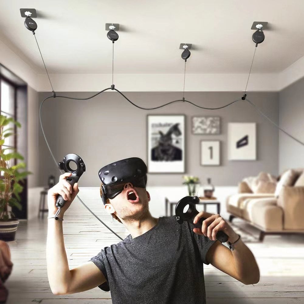
AR/VR devices combine high-speed displays, cameras, sensors, wireless modules and processors inside a compact mechanical structure. The interconnect therefore needs to handle high-speed signals while fitting into limited space and maintaining electrical and mechanical stability.
Micro coaxial cable assemblies can address these requirements through a combination of high-density routing, controlled impedance, individual shielding, small cable diameter and flexible construction.
If → the device contains multiple displays, cameras and sensors
Then → evaluate a high-density cable architecture that can route multiple signal paths within the available space
Why → the number of electrical connections can increase faster than the available internal routing area.
If → high-speed display or camera signals must pass through a compact device
Then → evaluate impedance, attenuation, connector transition and cable length together
Why → high-speed signal integrity depends on the complete transmission path.
If → wireless modules and high-speed digital circuits operate close to the cable
Then → evaluate individual shielding, overall shielding and grounding
Why → electromagnetic coupling can affect signal integrity and coexistence between adjacent circuits.
If → the cable is routed through hinges, adjustable headsets or moving optical assemblies
Then → define bend radius, flex cycles, cable OD and strain relief
Why → the cable must maintain its electrical function while following the mechanical movement of the device.
If → the device requires a smaller and lighter internal interconnect
Then → compare conductor size, shielding, connector density and cable architecture as a complete design
Why → reducing cable size should not create unacceptable electrical loss or mechanical reliability problems.
Modern AR and VR devices typically integrate multiple functional modules, including high-resolution displays, image sensors, depth cameras, microphones, antennas, and high-performance processors. These components continuously generate massive amounts of high-speed, high-frequency data that must be transmitted between modules stably and with low loss.
Traditional wire harnesses are increasingly limited in high-performance AR/VR applications due to their larger bulk, relatively high signal loss, and susceptibility to electromagnetic interference (EMI).
Utilizing AR/VR Micro Coax Cable Assemblies effectively addresses these challenges. Their primary advantages include:
As display resolutions advance from Full HD to 4K and beyond, and refresh rates climb to 90Hz, 120Hz, or even higher, stable high-speed signal transmission has become a critical factor in AR/VR product design.
With their outstanding electrical performance, micro coax cable assemblies provide a reliable interconnection solution for these high-speed applications.
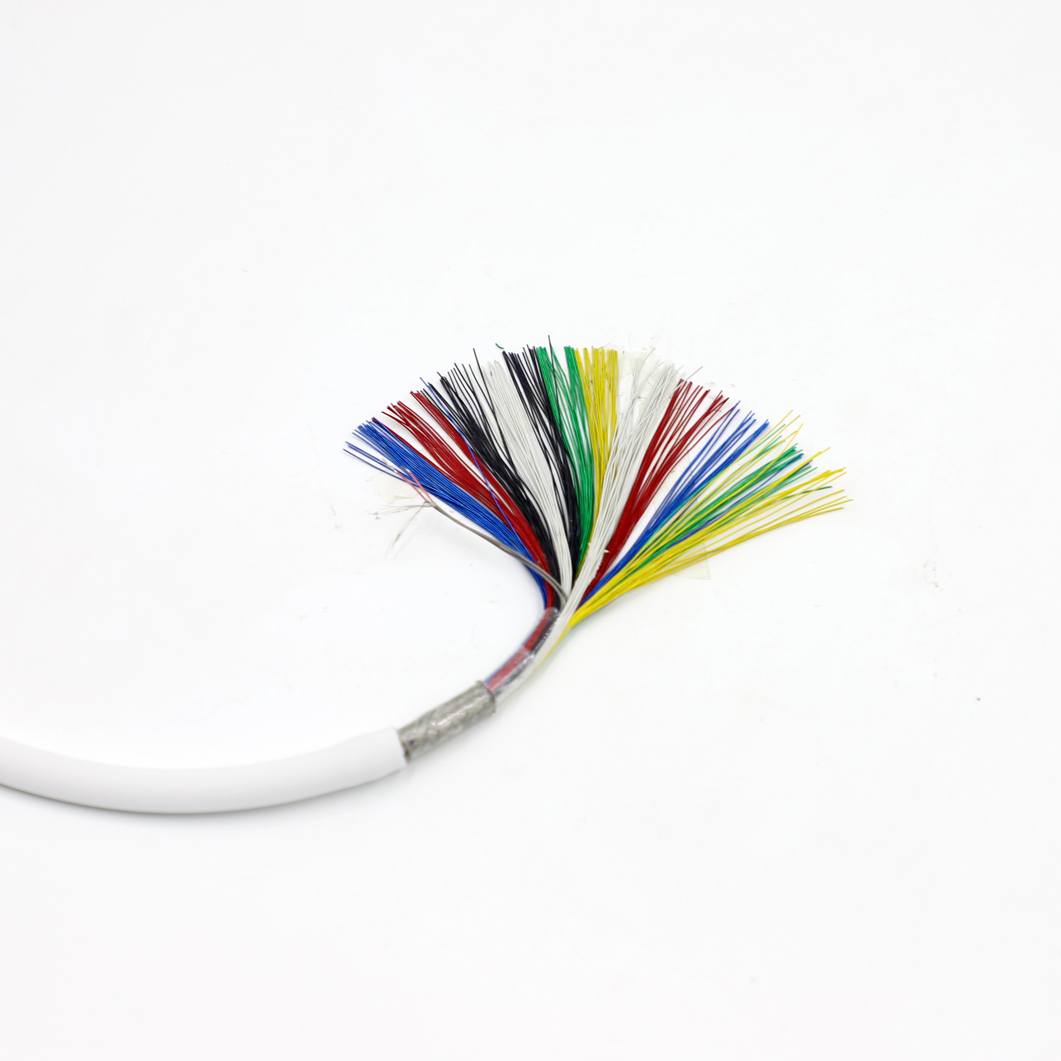
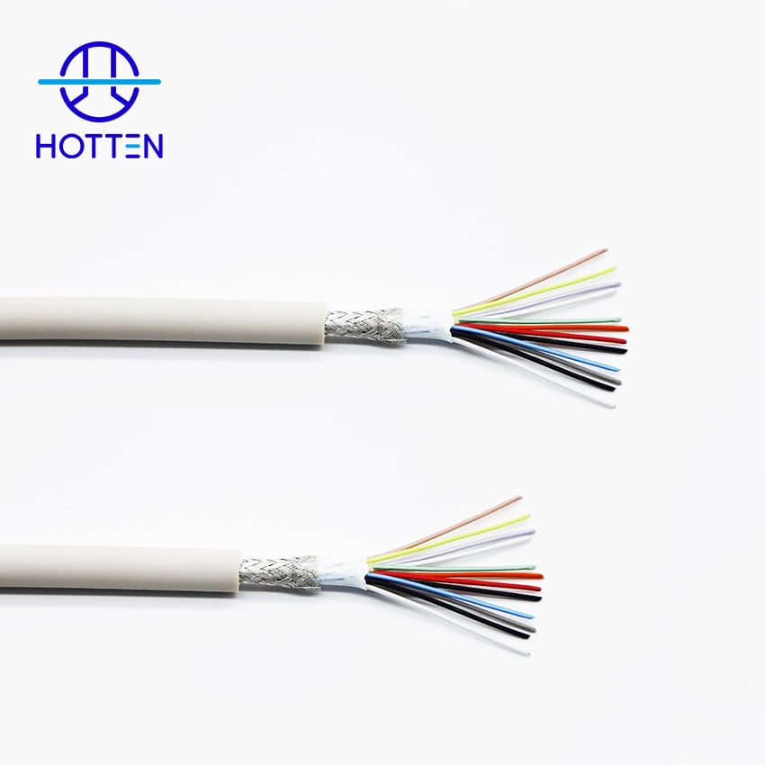
One of the primary reasons engineers specify Micro Coax Cables is their ability to achieve high-speed, stable, and low-loss data transmission. Compared to standard wires, each micro coax line typically consists of the following layers:
This coaxial structure maintains a stable characteristic impedance, effectively reducing insertion loss and signal reflection, thereby guaranteeing the quality of high-speed signal transmission.
Currently, micro coax cables are widely used in the following high-speed interfaces:
For AR/VR devices that simultaneously connect multiple cameras, displays, and sensors, these interfaces all demand stable, high-speed data transmission—a requirement that micro coax cables perfectly fulfill.
In highly integrated wearable electronics, electromagnetic interference (EMI) is always a critical factor affecting system stability. Each individual signal line in a Miniature Coax Cable features an independent shielding design, which significantly mitigates:
Excellent EMI shielding performance not only boosts overall system stability but also effectively prevents issues such as display flickering, image distortion, and communication anomalies. For AR/VR devices integrating Wi-Fi, Bluetooth, GNSS, and cellular communication modules, proper shielding design also enhances co-existence and compatibility between wireless modules, minimizing mutual interference.
Micro coax cables deliver stable and reliable transmission performance under high-frequency signals, characterized by:
These characteristics help the system maintain robust signal integrity (SI), meeting the stringent demands of modern high-speed display interfaces and image transmission protocols to provide stable data connectivity for AR/VR devices.
Space utilization is consistently one of the toughest challenges in wearable electronic product design. Compared to traditional cables, Micro Coax Cable Assemblies utilize finer conductor structures, drastically reducing cable dimensions while maintaining excellent electrical performance. Their main advantages include:
These advantages enable product designers to integrate more functional modules within limited internal spaces without increasing the physical size of the device.
Compared to rigid PCB connections, micro coax cable assemblies offer superior mechanical flexibility. In application scenarios such as:
Cables often need to endure tens of thousands of repeated bends. Properly engineered micro coax cable assemblies maintain stable electrical performance during long-term bending and dynamic use, effectively reducing the risk of conductor fatigue and breakage, thereby enhancing the long-term reliability of the entire device.
For an AR/VR project, the cable should be selected from the device architecture and signal requirements, rather than simply choosing the smallest available micro coaxial cable.
A practical framework is:
Device Architecture → Signal Type → Data Rate → Channel Count → Cable OD → Impedance → Shielding → Flexibility → Connector → Termination → Validation
An AR/VR device may contain several interconnected modules.
| Module | Typical Cable Requirement |
|---|---|
| Display | High-speed signal transmission |
| Camera | High-speed video / image signal |
| Depth Sensor | High-density data connection |
| Processor | High-speed internal interconnect |
| Wireless Module | EMI-aware routing |
| Audio Module | Signal / power connection |
| Sensor Module | Compact flexible routing |
If → several modules are distributed across the headset or glasses
Then → map the cable routes and interfaces before selecting the cable
Why → cable length, branch points and connector positions depend on the mechanical architecture.
AR/VR products may use different high-speed interfaces depending on the system design.
Potential interfaces include:
If → the interface has a defined electrical specification
Then → design the cable around the required impedance, data rate, channel count and interface geometry
Why → the cable must support the actual signaling architecture.
If → several interfaces coexist in the same assembly
Then → define each signal group's electrical and shielding requirements separately
Why → a display link, camera link and power path do not necessarily have the same cable requirements.
The same cable architecture may perform differently as transmission distance changes.
Important parameters include:
| Parameter | Engineering Question |
|---|---|
| Data Rate | What signaling speed must be supported? |
| Cable Length | What is the finished transmission distance? |
| Attenuation | What signal loss can the system tolerate? |
| Differential Impedance | What target is required? |
| Crosstalk | How much interaction is acceptable? |
| Skew | Is timing consistency important? |
If → the cable is short and the system has adequate signal margin
Then → evaluate whether a standard micro coax construction satisfies the requirement
Why → not every short interconnect requires the same level of optimization.
If → the cable is longer or the data rate is higher
Then → evaluate attenuation, impedance, skew and connector losses together
Why → total signal integrity depends on the complete electrical path.
A micro coaxial cable normally consists of:
Center Conductor
→ Dielectric
→ Shield
→ Outer Jacket
For high-speed applications, the physical relationship between these layers matters.
If → the conductor and dielectric geometry remain stable
Then → the cable is easier to maintain within its intended impedance range
Why → transmission-line behavior depends on the physical geometry.
If → cable OD is reduced significantly
Then → review conductor size, dielectric structure and shielding together
Why → cable miniaturization changes multiple electrical and mechanical variables at once.
Compact AR/VR devices can place high-speed signal paths close to:
If → several sensitive signal paths are routed closely together
Then → evaluate individually shielded micro coaxial structures
Why → individual shielding can help isolate adjacent signal paths.
If → wireless and high-speed digital circuits share a small internal volume
Then → evaluate shield termination and grounding together with the cable construction
Why → shielding effectiveness depends on the complete signal path and its interfaces.
The electrical path is not simply:
Cable
It is:
Cable → Termination → Connector → PCB
If → the micro coaxial cable meets the target impedance but the connector launch is poorly controlled
Then → investigate the complete transition
Why → a local discontinuity can introduce reflections even when the cable itself is within specification.
If → different connector types are used for displays and cameras
Then → validate each cable/connector combination separately
Why → connector geometry contributes to the finished signal path.
For additional impedance-control guidance:
What Is Cable Impedance and Why Does It Matter in High Frequency Cable Assemblies?
A smaller cable does not automatically mean a smaller finished assembly.
The total integration envelope also includes:
Cable OD + Connector + Termination + Strain Relief + Routing Clearance
If → internal device space is extremely limited
Then → evaluate cable OD and connector footprint together
Why → the connector can become the dominant space requirement.
If → the cable must pass through a hinge or narrow mechanical channel
Then → evaluate the complete routing envelope
Why → the assembly needs enough clearance to move without excessive local stress.
AR/VR devices may require cable movement around:
If → the cable moves repeatedly during normal use
Then → define bend radius, flex cycle requirement and movement pattern
Why → “flexible cable” does not define the actual mechanical load.
If → the cable is repeatedly bent close to a connector
Then → define strain relief and local bend geometry
Why → the connector transition can become a high-stress region.
For broader flex-life validation:
How Flex-Life Testing Helps Medical Cable Assemblies Maintain Performance After Repeated Bending
AR/VR products often contain both displays and cameras, but their cable requirements may differ.
If → the cable connects a high-resolution display
Then → define data rate, differential impedance, skew, attenuation and connector configuration
Why → display links can be sensitive to timing and transmission losses.
If → the cable connects a camera or depth sensor
Then → define interface type, channel count, cable length, shielding and mechanical routing
Why → image-data transmission may require a different channel architecture from the display interface.
This distinction allows the same AR/VR product to use different cable constructions within one device.
Different signaling architectures can have different electrical requirements.
| Interface | Engineering Factors to Define |
|---|---|
| MIPI D-PHY | Lane count / differential structure / interface geometry |
| MIPI C-PHY | Channel architecture / high-speed signaling requirements |
| LVDS | Differential impedance / skew / shielding |
| eDP | Lane structure / data rate / impedance / connector |
| USB | Data rate / impedance / connector / power |
| Camera Interface | Signal architecture / channel count / shielding |
If → two interfaces use different signaling requirements
Then → evaluate their cable structures independently
Why → similar physical cable dimensions do not necessarily mean identical electrical requirements.
For compact electronic products, OEM engineers may compare:
FPC
vs.
FFC
vs.
Micro-Coaxial Cable Assembly
The right choice depends on the system.
| Requirement | FPC | FFC | Micro-Coaxial Cable |
|---|---|---|---|
| Planar Routing | Strong fit | Strong fit | Flexible 3D routing |
| High-Density Signal Paths | Application-dependent | Application-dependent | Suitable for dense individual channels |
| Individual Shielding | Design-dependent | Limited / application-dependent | Available by coaxial construction |
| 3D Routing | Moderate | Limited | Strong |
| Dynamic Movement | Design-dependent | Application-dependent | Suitable for selected dynamic applications |
| Fine Routing | Good | Good | Good |
| Connector Integration | FPC connector | FFC connector | Micro coax connector / custom termination |
If → the device requires flat, planar routing
Then → evaluate FPC or FFC
Why → planar structures can simplify some internal layouts.
If → the device requires dense three-dimensional routing with individually controlled signal paths
Then → evaluate micro coaxial cable assembly
Why → separate coaxial channels can provide controlled transmission paths in compact 3D layouts.
For the broader comparison:
AR/VR devices can contain processors, displays and wireless modules that generate heat inside a compact enclosure.
If → internal temperature varies significantly during operation
Then → evaluate cable materials, impedance stability and connector performance across the relevant temperature range
Why → compact electronics can create temperature gradients within a small routing area.
If → the cable is exposed to sweat, skin contact or other environmental conditions
Then → evaluate jacket material and environmental durability according to the actual product design
Why → wearable applications can expose external cable sections to conditions different from internal electronic interconnects.
A useful qualification sequence is:
Prototype Assembly
→ Initial Electrical Test
→ Mechanical Installation
→ Dynamic Movement
→ Thermal / Environmental Test
→ Post-Test Electrical Validation
→ Final Inspection
Potential electrical checks include:
If → the cable passes bench testing but the assembled device shows signal problems
Then → evaluate cable routing, connector transitions, EMI environment and mechanical deformation
Why → system installation can create conditions not represented by standalone cable testing.
| Category | Recommended Information |
|---|---|
| Device Type | AR glasses / VR headset / XR device |
| Module | Display / Camera / Sensor / Other |
| Interface | MIPI / LVDS / eDP / USB / Other |
| Data Rate | Required signaling speed |
| Channel Count | Number of signal paths |
| Differential Impedance | Required value |
| Attenuation | Maximum acceptable loss |
| Skew | Required tolerance |
| Cable Length | Nominal + tolerance |
| Cable OD | Maximum allowable dimension |
| Conductor | AWG / material / construction |
| Dielectric | Material / structure |
| Shielding | Individual / overall |
| Connector | Manufacturer / part number |
| Connector Pitch | Required interface density |
| Pinout | Required mapping |
| Bend Radius | Minimum radius |
| Flex Cycles | Required endurance |
| Weight | Maximum assembly weight if applicable |
| Temperature | Operating range |
| Mechanical Routing | Available space / path |
| Testing | Electrical / mechanical / environmental |
| Production | Prototype / pilot / mass production |
If → the RFQ only states “micro coaxial cable for VR headset”
Then → add interface, data rate, cable length, OD, connector, shielding and flex requirements
Why → the application name alone does not define the complete cable assembly.
| Supplier Capability | What to Evaluate |
|---|---|
| Fine-Wire Capability | Required conductor sizes |
| Micro Coax Construction | High-density cable structures |
| Shielding | Individual / overall shielding |
| Connector Assembly | Fine-pitch termination |
| DFM | Mechanical and electrical design review |
| Prototype | Engineering sample development |
| Testing | Impedance / attenuation / signal integrity |
| Flex Validation | Dynamic movement capability |
| Production | Process repeatability |
| Quality | Inspection and traceability |
If → the supplier provides only standard micro coaxial cable
Then → evaluate whether it can customize cable length, shielding, connector, termination and routing
Why → AR/VR assemblies often require integration around the device's specific mechanical architecture.
If → the supplier can provide prototypes but not production validation
Then → review how the qualified design will be transferred into volume manufacturing
Why → prototype capability and production repeatability are separate requirements.
Hotten specializes in the R&D and manufacturing of micro coax cable assemblies and custom wire harnesses, providing tailored interconnection solutions for consumer electronics, medical devices, and other high-performance electronic products.
Leveraging years of micro coax product development experience, in-house manufacturing capabilities, and a comprehensive quality management system, we provide one-stop technical support—from solution design and sample development to mass production. We are dedicated to helping OEM/ODM customers improve product development efficiency and supply chain reliability.
 Hot News
2026-09-17
2026-09-04
2025-12-17
2025-12-11
2025-12-05