 EN
EN
Quick Links

Home > News > Company news
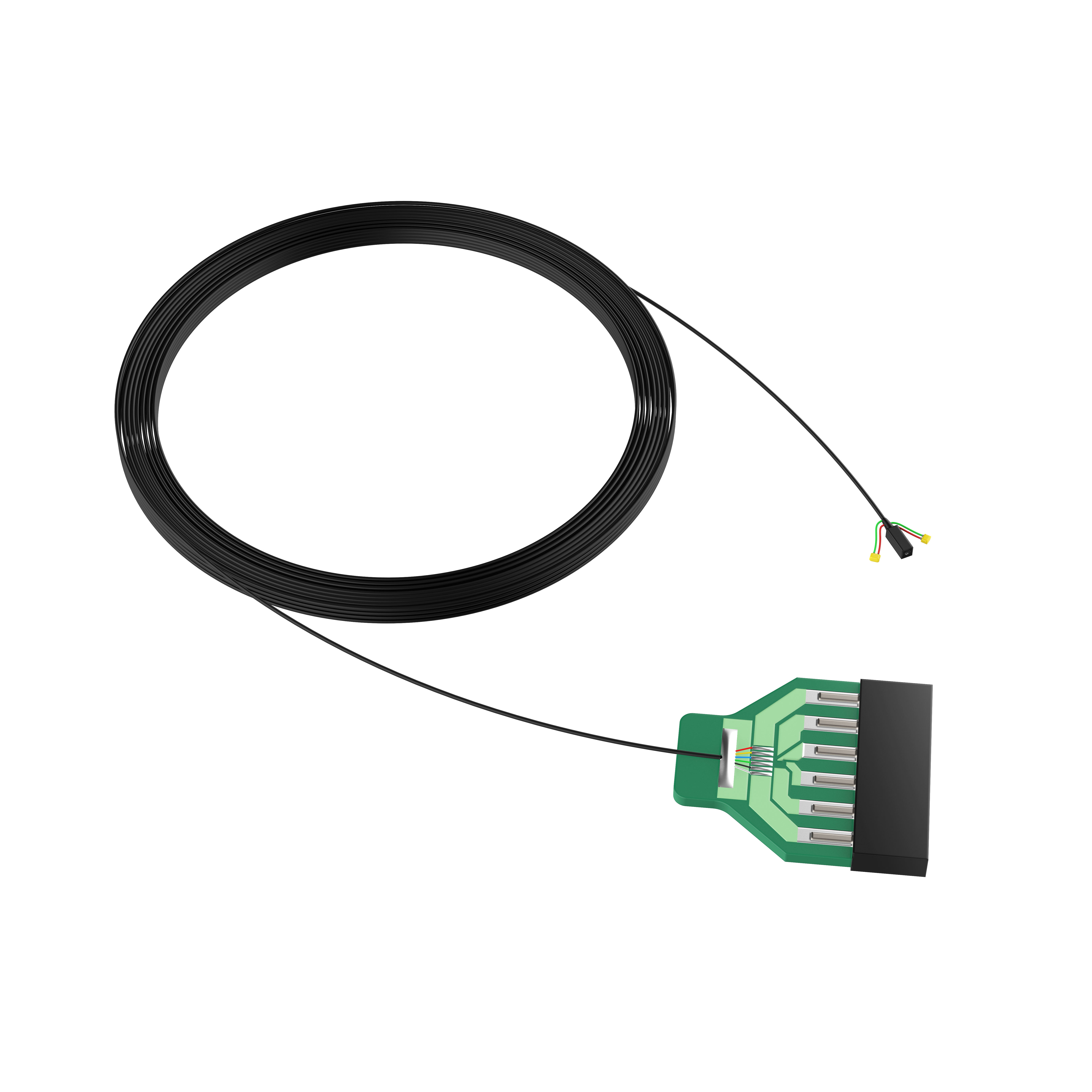
Micro coaxial cable assemblies help miniature endoscopic imaging systems maintain reliable signal transmission by combining small cable dimensions, controlled electrical characteristics, shielding, and flexible mechanical construction within a highly space-constrained interconnect. The appropriate cable design depends on the required signal characteristics, transmission length, available routing space, bending conditions, and termination method.
For ultra-miniature endoscopic systems, engineers commonly evaluate factors such as conductor size, cable outer diameter, impedance, attenuation, capacitance, shielding, and mechanical flexibility together rather than optimizing a single parameter. For example, finer conductors can help reduce cable size, but the final design still needs to be evaluated for resistance, attenuation, mechanical reliability, and the required transmission distance. More background on this relationship is available in How Does AWG Affect Micro Coaxial Cable Performance?.
The dielectric and insulation structure is also part of the signal-transmission design. Different insulation technologies can affect the electrical and mechanical characteristics of a micro-coaxial cable, so material selection should be considered together with impedance and flexibility requirements. See How to Select the Right Foaming Technology for Micro Coaxial Cable Insulation?.
For applications requiring a customized miniature medical interconnect, see HOTTEN's Endoscope Cable solutions.
In modern minimally invasive surgery, endoscopic devices need to pass through narrow natural anatomical pathways. By placing a miniature CMOS image sensor (such as the OmniVision OVM6946 camera module) directly at the distal end of an endoscope or diagnostic catheter, physicians can capture real-time high-definition images inside the human body.
While sensor miniaturization has significantly expanded diagnostic capabilities, it has also introduced considerable engineering challenges for the interconnection system.
Inside an insertion tube with a typical outer diameter of less than 2.0 mm, extremely limited cross-sectional space must accommodate multiple functional components, including working channels, LED illumination systems, steering wires, and electrical interconnects.
The medical miniature coaxial cable assembly connecting the distal camera module and the proximal camera control unit (CCU) often needs to occupy space measured in fractions of a millimeter. At the same time, it must reliably transmit uncompressed video data, power signals, and clock signals over transmission lengths ranging from more than 1.5 meters to 5 meters, without signal degradation or physical failure.
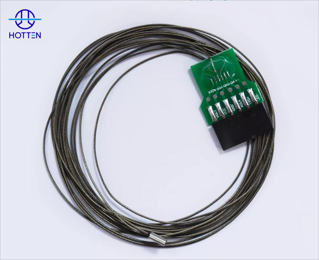
In miniature endoscopic instruments, the cable assembly is far more than a passive connection component. It functions as a critical structural and electrical subsystem that directly determines device performance.
Signal Integrity:
Endoscopic image sensors require a clean high-frequency signal path. The cable assembly must maintain stable characteristic impedance and low signal attenuation to prevent image artifacts, frame loss, or electromagnetic interference (EMI) noise.
Mechanical Integration:
The cable assembly must withstand small-radius bending, adapt to complex anatomical pathways, and achieve seamless connections between miniature sensor pads and proximal PCB or customized connectors.
System Reliability:
Disposable and reusable endoscopes experience repeated bending, thermal stress, and sterilization cycles. Cable electrical performance must remain consistent throughout the service life.
Challenge 1: Ultra-Thin Structural Design Under Limited Space Conditions
Engineers utilize miniature coaxial cable structures based on ultra-fine conductors such as 42 AWG to 48 AWG silver-plated copper alloy wires. A single micro coaxial cable can achieve an outer diameter as small as 0.16 mm to 0.3 mm.
Integrating multiple micro coaxial cables into a multi-core miniature medical cable requires precise tension control and customized extrusion jackets.
Challenge 2: Ensuring Signal Integrity for High-Definition Medical Imaging
High-frequency signal transmission through ultra-fine conductors faces higher resistance and attenuation. Without proper electrical design, cables up to 5 meters may experience high-frequency loss, impedance mismatch reflection, and electromagnetic interference.
Key design features include:
- Precise 50Ω or 75Ω impedance control
- High-coverage spiral-wrapped or braided shielding with up to 90–95% coverage
- Low dielectric constant FEP/PFA insulation materials
Challenge 3: Flexibility, Bending Life, and Biocompatibility
Endoscope insertion tubes experience continuous bending, rotation, and twisting. High-performance medical camera cables require low elastic memory and flexible insulation structures to withstand thousands of bending cycles.
Selecting a micro-coaxial cable for a miniature endoscopic imaging system requires balancing electrical performance, mechanical flexibility, dimensional constraints, and termination requirements. A smaller cable is not automatically the best choice because conductor size, cable construction, shielding, routing, and termination all influence the final assembly performance.
If the insertion tube provides extremely limited routing space, engineers may evaluate finer conductors and smaller cable OD. This can help reduce the occupied cross-sectional area, but conductor size should not be considered independently from transmission requirements.
If the required transmission distance is relatively long, signal attenuation and electrical resistance should be evaluated together with cable size. The appropriate AWG should therefore be selected according to the complete system requirements rather than simply choosing the smallest available conductor.
For a more detailed explanation of conductor-size trade-offs, see How Does AWG Affect Micro Coaxial Cable Performance?.
If the endoscope requires repeated bending, rotation, or twisting, the cable assembly must be evaluated as both an electrical and mechanical subsystem. Impedance and attenuation are important for signal transmission, but bending radius, flex cycles, shielding stability, and strain relief also affect long-term reliability.
If high-frequency signals are transmitted through a compact cable structure, impedance consistency and insulation construction should be considered together. Cable geometry and dielectric materials can influence the electrical characteristics of the transmission path.
For related information on insulation selection and dielectric performance, see How to Select the Right Foaming Technology for Micro Coaxial Cable Insulation?.
In miniature endoscopic systems, the cable cannot be evaluated separately from the termination area. Sensor-side connections may require precision soldering at extremely small pads, while the proximal end may connect to a PCB, interposer, or miniature connector.
If the cable is designed for direct connection to a miniature image sensor, the available pad size, conductor pitch, termination process, strain relief, and required assembly tolerance should be confirmed during the design stage.
A practical engineering review should therefore confirm:
| Requirement | Parameters to Confirm |
|---|---|
| Miniaturization | AWG, cable OD, core count, routing space |
| Signal Transmission | Impedance, attenuation, capacitance, transmission length |
| EMI Control | Shielding structure, shielding coverage, termination |
| Mechanical Performance | Bend radius, flex cycles, torsion, strain relief |
| Sensor Connection | Pad size, conductor pitch, soldering method |
| Proximal Interface | Connector type, PCB interface, termination configuration |
The final cable specification should be based on the priority of the endoscopic system:
If minimum diameter is the primary constraint → evaluate finer conductor and insulation structures → then verify attenuation, impedance, and mechanical reliability.
If repeated bending is the primary constraint → evaluate cable construction, shielding, insulation, and strain relief together → then validate the complete assembly through mechanical testing.
If signal integrity is the primary constraint → evaluate impedance, attenuation, capacitance, shielding, cable length, and termination geometry together → then verify the complete signal path rather than the cable core alone.
For related medical micro-coaxial applications, see Micro-Coaxial Cable Solutions for Medical Ultrasound Imaging Systems.
For customized miniature medical interconnects, see HOTTEN's Endoscope Cable and Micro Coaxial Cable solutions.
The OmniVision OVM6946 is an industry-standard miniature medical camera module using a 1/18-inch CMOS image sensor with a size of only 0.62 mm × 0.62 mm.
The OVM6946 cable assembly typically requires four to six independent conductors for power supply, ground, clock signals, and analog/digital video data.
Main engineering challenges:
1. Direct sensor-end micro termination requiring microscope-level precision.
2. Balanced mechanical performance requiring ultra-thin but durable cable structures.
For a miniature endoscopic imaging project, the cable should be treated as part of the camera-to-electronics interconnect, not simply as a small wire.
A practical engineering framework is:
Camera / Sensor → Signal Interface → Cable Architecture → Cable OD → Impedance / Attenuation → Shielding → Flexibility → Termination → Environmental Conditions → Validation
The current HOTTEN article already identifies the main endoscopic constraints as limited space, high-frequency transmission, bending, rotation, twisting, shielding and precision sensor-side termination.
The cable design should begin with the actual imaging module.
For example, the current HOTTEN article uses the OVM6946 camera module as an application example and describes a sensor-side connection requiring very small termination areas.
OEM engineers should first define:
| Parameter | Engineering Question |
|---|---|
| Camera Module | Which sensor / camera module is used? |
| Signal Interface | Analog / digital / mixed? |
| Power | What supply requirements are required? |
| Clock | Is a clock or timing signal routed through the cable? |
| Video Signal | What transmission characteristics are required? |
| Channel Count | How many independent conductors / coaxial channels? |
| Sensor Pad | What pad size and pitch are available? |
| Proximal Interface | PCB / FPC / connector / other? |
If → the camera module has extremely small contact pads
Then → define the termination method and conductor pitch before finalizing the cable structure
Why → the sensor interface may impose tighter dimensional constraints than the cable body itself.
The current HOTTEN article describes miniature endoscopic insertion tubes with extremely limited internal space, with the cable occupying only a fraction of the available cross-sectional area. It also gives an example of single micro coaxial cable OD in the approximate 0.16–0.30 mm range.
For OEM engineering, define:
If → the insertion tube has very limited routing space
Then → define maximum cable OD before selecting conductor and shielding construction
Why → cable diameter is a system-integration constraint.
If → multiple signal channels must fit into the same space
Then → evaluate multi-coax architecture and channel density
Why → the cable structure must accommodate all required signal paths within the available mechanical envelope.
The current article already explains that finer conductors can reduce cable dimensions but can increase resistance and attenuation, especially over longer transmission distances. It discusses 42–48 AWG micro coaxial structures in its endoscopic examples.
The selection should therefore be:
Required OD
Transmission Distance
Signal Requirements
Mechanical Reliability
rather than simply:
Smallest conductor available.
If → the endoscope has an extremely tight space constraint
Then → evaluate finer conductors
Why → smaller conductors can help reduce cable dimensions.
If → the camera-to-CCU transmission path becomes relatively long
Then → evaluate resistance, attenuation and complete signal loss together with AWG
Why → conductor miniaturization can create electrical trade-offs.
The current HOTTEN article describes endoscopic cable transmission lengths in the approximate 1.5 m to 5 m range for its application example.
An endoscopic camera cable may contain a mixture of:
This means one cable assembly may contain several electrically different requirements.
If → the cable contains controlled-impedance signal paths
Then → define impedance and attenuation requirements separately from power conductors
Why → not every conductor in a mixed cable assembly has the same electrical function.
If → multiple high-speed channels are routed together
Then → evaluate channel isolation, shielding and electrical consistency
Why → adjacent signal paths can interact in a dense cable structure.
The current HOTTEN page specifically identifies power, ground, clock and video-related connections in its OVM6946 application example.
The current article states that endoscopic micro coaxial cables may use 50Ω or 75Ω impedance structures and should be evaluated for attenuation and reflection when transmitting high-frequency signals.
For OEM specification:
| Electrical Requirement | What to Define |
|---|---|
| Impedance | Nominal value |
| Frequency | Operating range |
| Attenuation | Maximum acceptable loss |
| Capacitance | Target / maximum |
| Return Loss | Required limit if applicable |
| Cable Length | Finished signal path |
| Electrical Test | Required measurement method |
If → the signal path has a controlled impedance requirement
Then → define impedance together with frequency and acceptance criteria
Why → “50Ω cable” by itself does not define the complete RF performance.
If → the cable is relatively long for the application
Then → include attenuation in the initial specification
Why → a compact cable can still produce unacceptable signal loss over a longer transmission path.
相关基础文章可以连接:
What Is Cable Impedance and Why Does It Matter in High Frequency Cable Assemblies?
The current HOTTEN article describes spiral-wrapped or braided shielding with stated coverage figures of up to 90–95% for its example constructions.
但 OEM 不应该只问:
“How much shielding coverage?”
还应该确认:
If → several high-frequency channels are packed together
Then → evaluate individual-channel isolation as well as overall shielding
Why → external EMI and channel-to-channel coupling are different problems.
If → shielding is increased significantly
Then → check cable OD and flexibility again
Why → additional shielding may affect the mechanical structure and available routing space.
这篇可以自然连接上一轮的:
How Low-Noise Medical Cable Assemblies Support More Accurate Diagnostic Signals
For miniature endoscopes, the sensor-side termination can be extremely small.
The current OVM6946 example describes direct sensor-end micro termination requiring microscope-level precision. HOTTEN also lists precision microsoldering, FPC and miniature connector termination among its capabilities.
Relevant controls may include:
If → the camera module has very small pads
Then → validate the termination process during prototype development
Why → the sensor-side connection can become the most dimensionally sensitive part of the assembly.
If → termination is mechanically exposed
Then → evaluate strain relief and encapsulation
Why → local movement can concentrate stress at the sensor connection.
An endoscopic cable has two different interface environments:
Distal End
→ Miniature Camera / Sensor
and
Proximal End
→ PCB / FPC / Connector / Control Unit
These two ends do not necessarily need identical termination methods.
If → the distal end connects directly to a miniature sensor
Then → prioritize conductor pitch, pad alignment and micro-termination capability
Why → sensor packaging creates a very small connection area.
If → the proximal end connects to a PCB or standard connector
Then → prioritize connector fit, pinout, strain relief and assembly repeatability
Why → the proximal interface may have different dimensional and mechanical requirements.
This distinction is already implicit in the current OVM6946 example, which describes sensor-side micro termination and proximal PCB / connector interfaces.
The current article states that endoscope insertion tubes experience continuous bending, rotation and twisting.
So an RFQ should not simply say:
Flexible medical cable
Instead define:
| Mechanical Requirement | What to Specify |
|---|---|
| Bend Radius | Minimum radius |
| Bend Angle | Required movement |
| Flex Cycles | Required endurance |
| Torsion | Rotation / twist |
| Motion Speed | Movement frequency |
| Fixation | Cable mounting points |
| Strain Relief | Required protection |
| Environmental Condition | Temperature / humidity / other |
If → the cable experiences repeated bending and twisting
Then → validate the complete assembly under representative combined motion
Why → endoscopic cable loading is often not a simple single-axis bend.
这可以直接连接:
How Flex-Life Testing Helps Medical Cable Assemblies Maintain Performance After Repeated Bending
The current article notes that disposable and reusable endoscopes may experience different environmental and mechanical conditions, including thermal stress and sterilization cycles.
If → the assembly is designed for a reusable endoscope
Then → define the actual cleaning, disinfection and sterilization exposure
Why → repeated environmental exposure can affect insulation, jacket, termination and mechanical properties.
If → the assembly is designed for single-use equipment
Then → define the environmental exposure associated with storage, transport and intended use
Why → the qualification profile should match the actual product lifecycle.
不要直接把某一个 sterilization cycle 数字当成所有 endoscope cable 的通用标准。
For a miniature endoscopic cable, testing only the raw cable is not enough.
A useful validation path is:
Camera-Side Termination
→ Micro Coaxial Cable
→ Proximal Connector / PCB
→ CCU Interface
→ Signal Validation
Potential tests may include:
| Test | Purpose |
|---|---|
| Continuity | Verify electrical connections |
| Pin / Wire Sequence | Verify correct mapping |
| Impedance | Verify controlled transmission structure |
| Attenuation | Verify signal loss |
| Capacitance | Verify electrical characteristics |
| Insulation | Verify insulation performance where applicable |
| Shielding | Verify relevant EMI / continuity requirements |
| Flex-Life | Evaluate repeated movement |
| Tensile | Evaluate mechanical strength |
| Dimensional Inspection | Verify integration dimensions |
| Visual Inspection | Verify workmanship |
The current HOTTEN article states that its endoscopic cable assembly development includes 100% electrical testing, impedance testing, signal attenuation verification, tensile testing and bending-life validation.
A useful qualification sequence is:
Initial Electrical Test
→ Bending / Torsion Testing
→ Post-Test Electrical Measurement
→ Visual / Dimensional Inspection
→ Failure Analysis if Required
If → the cable remains electrically continuous after flex testing
Then → check impedance, attenuation and other application-relevant parameters
Why → continuity alone does not prove that high-speed signal performance remains unchanged.
If → attenuation or impedance changes after mechanical stress
Then → investigate conductor movement, dielectric deformation, shielding and termination
Why → electrical degradation can precede complete mechanical failure.
This is the most important procurement addition to the article.
| Category | Recommended Information |
|---|---|
| Camera Module | Part number / sensor |
| Signal Interface | Analog / digital / mixed |
| Signal Type | Video / clock / power / control |
| Frequency | Operating range |
| Impedance | Nominal value if controlled |
| Attenuation | Maximum acceptable loss |
| Capacitance | Target / maximum |
| Channel Count | Number of signal paths |
| Conductor | AWG / material / construction |
| Cable OD | Maximum allowable OD |
| Cable Length | Nominal + tolerance |
| Shielding | Individual / overall / other |
| Dielectric | Material / structure |
| Bend Radius | Minimum required |
| Flex Cycles | Required cycle count |
| Torsion | Required rotation / twist |
| Sensor Interface | Pad size / pitch |
| Distal Termination | Solder / weld / other |
| Proximal Interface | PCB / FPC / connector |
| Strain Relief | Required structure |
| Environment | Temperature / humidity |
| Cleaning / Sterilization | Applicable process |
| Testing | Electrical / mechanical / environmental |
| Production | Prototype / pilot / mass production |
If → the RFQ only specifies “micro coaxial cable for endoscope”
Then → request camera module, signal interface, cable OD, length, connector, bend requirements and testing requirements
Why → the application name alone does not define the complete interconnect design.
A supplier evaluation should cover both cable capability and assembly capability.
| Evaluation Area | What to Check |
|---|---|
| Fine-Wire Capability | AWG range / conductor handling |
| Cable Construction | Micro coax / multi-coax structures |
| Insulation | Dielectric options / dimensional control |
| Shielding | Individual / overall / termination |
| Micro-Termination | Sensor-side assembly capability |
| Connector Assembly | Proximal interface capability |
| Testing | Electrical + mechanical validation |
| DFM | Design review capability |
| Prototype | Sample development process |
| Production | Process repeatability |
| Quality | Inspection / traceability / records |
If → the supplier can make a very small cable but lacks miniature termination capability
Then → evaluate the supplier's complete assembly capability
Why → the limiting process may be at the sensor-side connection rather than the cable extrusion stage.
If → the supplier can make prototypes but cannot show production controls
Then → review process validation and inspection capability before volume qualification
Why → prototype capability and production consistency are different requirements.
Hotten Electronic Technology specializes in customized ultra-fine micro coaxial cables and high-precision cable assemblies for medical imaging applications.
Customized Cable Structure:
- 42 AWG to 48 AWG micro coaxial structures
- High-strength copper alloy conductors
- Customized served or braided shielding structures
Micro-Termination and Assembly Integration:
- Precision micro soldering for CMOS modules including OVM6946 and OVM6948
- FPC and miniature connector termination
- Medical-grade epoxy encapsulation and strain relief solutions
Engineering and Quality Support:
- Rapid prototype development
- Design for Manufacturing (DFM) guidance
- 100% electrical testing, impedance testing, signal attenuation verification, tensile testing, and bending life validation
Hotten provides customized medical micro coaxial cable assembly solutions for miniature endoscopic imaging systems, helping medical device manufacturers achieve reliable high-speed signal transmission, compact integration, and long-term system performance.
 Hot News
2026-09-17
2026-09-04
2025-12-17
2025-12-11
2025-12-05