 EN
EN
Quick Links

Home > News > Company news
The right insulation technology for a micro coaxial cable depends on the application's electrical target, mechanical movement, environmental exposure and production requirements.
For micro coaxial cables in the 38 AWG to 46 AWG range, three insulation approaches can be considered: physical foaming, lotus foam and expanded PTFE (ePTFE) tape.
In the engineering comparison presented here:
Therefore, there is no universal insulation technology that is best for every micro coaxial cable. The selection should be based on the actual electrical, mechanical and environmental requirements of the cable assembly.
For the broader effects of conductor size on micro coaxial cable design, see How Does AWG Affect Micro Coaxial Cable Performance?.
In high-frequency micro coaxial cable design, the insulation layer affects more than mechanical protection. It also influences the dielectric environment around the conductor and therefore affects characteristic impedance, capacitance and high-frequency transmission performance.
In very small cable constructions, maintaining low signal attenuation and controlled impedance within a limited diameter requires careful insulation design.
One engineering approach is to introduce air void structures into the insulation to reduce the effective dielectric constant of the insulation material.
The three technologies compared in this article are:
They should be evaluated from four practical perspectives:
The following table summarizes the engineering differences described in this comparison.
| Engineering Factor | Physical Foaming | Lotus Foam | Expanded PTFE Tape |
|---|---|---|---|
| Typical dielectric constant in this comparison | 1.4–1.7 | 1.2–1.4 | 1.3–1.6 |
| Insulation structure | Uniform closed-cell structure | Open / semi-continuous pore structure | Node-and-fibril microporous structure |
| Impedance stability | Excellent | Medium; more affected by humidity | High |
| Dynamic flex capability | High | Medium to low | Good radial flexibility |
| Moisture resistance | High | Low | Application-dependent |
| Main advantage | Balanced electrical, mechanical and production performance | Very low dielectric constant | Thermal, chemical and specialized high-performance capability |
| Typical applications | Medical ultrasound, AR/VR, display buses, robotics | Static or limited-movement high-frequency systems | Aerospace, avionics, specialized RF, ultrasonic inspection |
The final cable design should still be evaluated as a complete construction rather than by insulation technology alone.
Physical foaming introduces high-pressure inert gas, typically nitrogen, into molten polymer or fluoropolymer during extrusion. Controlled pressure release then creates a closed-cell microstructure within the insulation.
The key benefit is balance.
A uniform closed-cell structure can provide a relatively stable dielectric environment while maintaining mechanical integrity. In the technical construction described here, physical foaming supports micro coaxial cables using fine conductors from approximately 38 AWG to 46 AWG.
The current comparison gives a dielectric constant range of approximately 1.4–1.7.
Because the closed-cell structure limits continuous pathways through the insulation, the construction can provide better resistance to environmental moisture migration than an open or semi-continuous pore structure.
If the application requires a balance of signal performance, flexibility, moisture resistance and production consistency → physical foaming is a strong candidate → because it does not optimize only one property at the expense of the others.
Typical applications described in this comparison include medical micro coaxial cable assemblies, industrial and robotics systems, RF systems and AR/VR equipment.
For medical applications, HOTTEN's Medical Equipment Cable Solutions include micro coaxial cable structures designed around impedance, capacitance, conductor construction, shielding, cable diameter and bending performance.
Lotus foam uses a specially designed extrusion structure to create a longitudinal pore network inside the insulation. The increased air volume fraction can produce a very low dielectric constant.
The comparison presented here gives a dielectric constant range of approximately 1.2–1.4.
A lower dielectric constant can be useful when the design is targeting specific high-frequency electrical characteristics.
However, the lowest dielectric constant is not automatically the best overall cable solution.
The pore structure can introduce greater environmental and mechanical sensitivity.
Under high humidity, semi-continuous pores may provide pathways for moisture penetration.
Under repeated or small-radius dynamic bending, the structure may also be more vulnerable to local deformation. The original engineering analysis identifies possible effects such as:
If the primary requirement is extremely low dielectric performance and the cable operates in a relatively static, controlled environment → lotus foam may be considered → because its lower dielectric constant can be valuable when dynamic mechanical and moisture exposure are limited.
It should therefore not be treated simply as a universal replacement for traditional physical foaming.
Expanded PTFE tape insulation is produced by stretching PTFE material to create a microporous structure consisting of interconnected nodes and fibrils.
This construction is different from conventional closed-cell foam.
The technical comparison presented here identifies:
The original comparison identifies a temperature capability from approximately −200°C to +260°C for the described construction.
If the application faces extreme thermal or chemical conditions or requires a specialized high-performance insulation structure → expanded PTFE tape may be appropriate → because thermal stability, chemical resistance and specialized mechanical behavior can become more important than cost or general-purpose manufacturability.
Typical application areas described in this comparison include:
Instead of asking:
Which insulation technology is the best?
A more useful engineering question is:
Which insulation technology best matches the actual operating conditions of the cable?
If the cable will experience repeated bending, movement or tight routing → prioritize mechanical stability and flex performance → physical foaming is generally more suitable than lotus foam in the comparison described here.
The relevant requirements may include:
If the cable will operate in humid or changing environmental conditions → prioritize moisture resistance → closed-cell physical foaming provides an advantage over the semi-continuous pore structure described for lotus foam.
If minimum dielectric constant is the primary target and mechanical movement is limited → lotus foam may be considered → provided that environmental and mechanical conditions are controlled.
If the cable must operate under specialized thermal or chemical conditions → evaluate expanded PTFE tape → because its thermal and chemical stability may be more important than general-purpose insulation performance.
If the project requires stable continuous manufacturing and repeat production → evaluate not only electrical performance but also process consistency, dimensional control and mechanical reliability → because the insulation structure must remain consistent across production.
Insulation technology is only one part of a micro coaxial cable.
A complete cable design also depends on:
For example, selecting a smaller conductor does not automatically produce the smallest finished cable. The final cable diameter depends on the complete coaxial structure.
For a broader discussion of conductor size and its effect on cable construction, see How Does AWG Affect Micro Coaxial Cable Performance?.
Engineers comparing compact interconnect technologies can also review FPC vs. FFC vs. Micro-Coaxial Cable Assembly: A Technical Comparison of High-Density Connection Solutions.
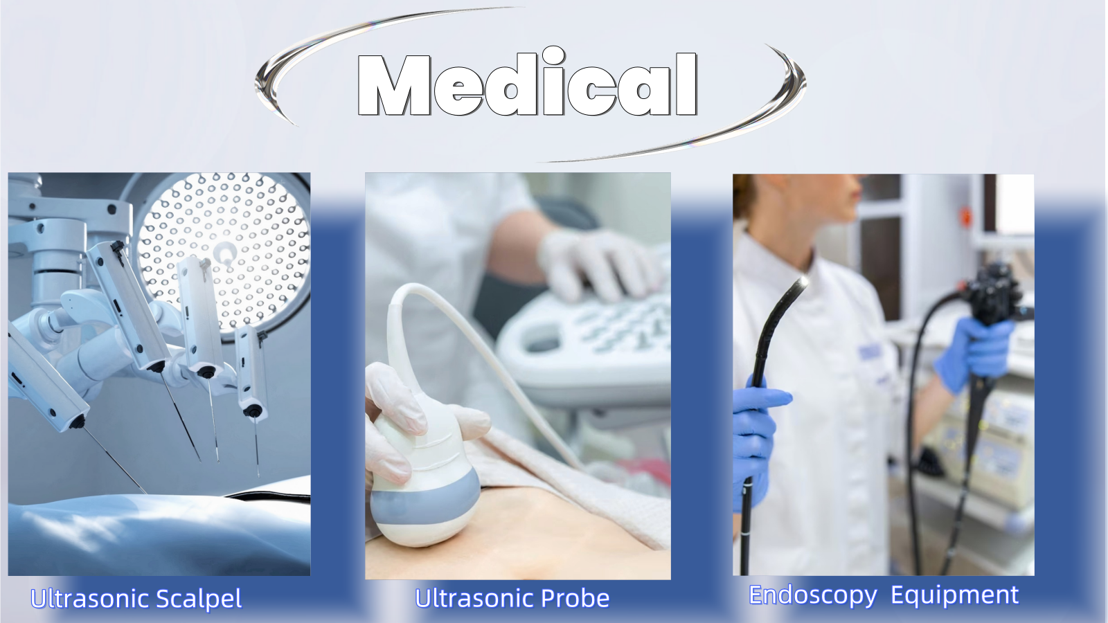
Medical imaging applications can combine high channel density, compact routing, signal integrity and repeated mechanical movement.
If the cable requires a balance of electrical performance, flexibility and production consistency → physical foaming may be considered as part of the complete micro coaxial cable design.
For application-level requirements, see HOTTEN Medical Equipment Cable Solutions.
Compact UAV and robotic systems may require small cable structures, lightweight routing, signal reliability and resistance to repeated movement.
If the cable must balance miniaturization, dynamic movement and signal transmission → the insulation structure should be evaluated together with conductor size, shielding and cable OD rather than selecting insulation based only on dielectric constant.
See HOTTEN UAV & Robotics Cable Solutions for application-level cable assembly requirements.
For high-frequency systems, dielectric characteristics, impedance consistency and attenuation become particularly important.
If electrical performance is the dominant requirement and mechanical movement is limited → lower-dielectric insulation technologies may be considered, but environmental and manufacturing requirements still need to be evaluated.
Before specifying micro coaxial cable insulation, confirm:
| Requirement | Questions to Confirm |
|---|---|
| Electrical | What impedance and frequency are required? |
| Conductor | What AWG, conductor material and construction are needed? |
| Insulation | What dielectric performance is required? |
| Mechanical | Is repeated bending required? What routing space is available? |
| Environment | Is humidity, temperature or chemical exposure significant? |
| Shielding | What EMI or shielding structure is required? |
| Dimensions | What cable OD and insulation thickness are acceptable? |
| Assembly | What connector, pinout and cable length are required? |
| Production | Is the project prototype, NPI or mass production? |
This approach helps prevent over-optimizing a single parameter while creating problems elsewhere in the cable assembly.
There is no universal insulation technology that is best for every micro coaxial cable.
Physical foaming provides a balanced engineering option when impedance stability, dynamic bending, moisture resistance and manufacturing consistency must all be considered.
Lotus foam can provide a lower dielectric constant, but its pore structure introduces greater sensitivity to moisture and mechanical movement.
Expanded PTFE tape is better suited to specialized high-performance applications where thermal stability, chemical resistance and specialized mechanical characteristics are major requirements.
The correct choice therefore depends on the complete application:
Electrical requirements + mechanical requirements + environmental conditions + cable construction + production requirements
For a customized micro coaxial cable assembly, insulation should be selected together with the conductor, shielding, cable diameter and connector configuration.
Explore HOTTEN's Micro Coaxial Cable Assembly solutions for customized cable structures and assembly requirements.
For an RFQ, provide the connector part number, pinout, cable length, AWG or conductor requirement, electrical specifications, routing requirements, drawing or sample, and expected quantity where available.
Engineering Comparison of Physical Foam, Lotus Foam, and Expanded PTFE Tape Technologies
In the design of high-frequency micro coaxial cables ranging from 38 AWG to 46 AWG, achieving low signal attenuation and precise characteristic impedance control (50 Ω or 75 Ω) within extremely limited dimensions requires advanced insulation engineering.
The fundamental engineering approach is to introduce air void structures into the insulation layer to significantly reduce the material’s relative dielectric constant.
This article compares the engineering selection logic of physical foaming, lotus foam, and expanded PTFE tape insulation technologies from three key perspectives:
- Electrical performance
- Dynamic bending reliability
- Environmental adaptability
Physical foaming technology relies on injecting high-pressure inert gas, typically nitrogen, directly into molten polymer or fluoropolymer materials during the extrusion process.
When the material exits the extrusion die, controlled pressure release creates a uniformly distributed closed-cell micro air bubble structure inside the insulation layer.
Core Technical Characteristics
Uniform Closed-Cell Geometry:
The independent cellular structure blocks continuous pathways inside the insulation layer, allowing the cable to maintain excellent structural integrity under mechanical compression.
Stable Dielectric Constant (1.4–1.7):
Provides predictable characteristic impedance control with excellent consistency between production batches.
Fine Conductor Compatibility:
Supports continuous extrusion with high concentricity over ultra-fine conductors ranging from 38 AWG to 46 AWG.
Because the closed-cell structure effectively prevents gas and moisture migration, physically foamed FEP/PFA insulation maintains excellent capacitance stability and low high-frequency attenuation during long-length continuous production.
Main Application Areas:
Medical Micro Coaxial Cable Assemblies, Industrial and Robotics Applications, RF and AR/VR Systems.
Lotus foam technology utilizes specially designed extrusion dies to create a parallel pore network extending longitudinally through the insulation layer, forming a structure similar to the cross-section of a lotus root.
Electrical Performance Advantages:
This structure significantly increases the internal gas volume fraction (Void Fraction) within the insulation layer, enabling an extremely low dielectric constant.
Key Engineering Trade-offs and Limitations
Moisture Sensitivity:
Unlike closed-cell structures, the semi-continuous pore network inside lotus foam can become a pathway for environmental moisture penetration under high-humidity conditions.
Mechanical Vulnerability Under Flexure:
The high void ratio reduces compressive strength. Under long-term dynamic bending or small-radius bending conditions, local cellular structures may collapse, resulting in inner conductor eccentricity, impedance dips, and signal reflection.
Engineering Recommendation:
Lotus foam should not simply be considered the next-generation replacement technology for traditional foamed fluoropolymer insulation. Its application should be limited to static or short-distance high-frequency transmission environments with controlled humidity and limited mechanical movement.
Expanded PTFE tape insulation is manufactured by mechanically stretching extruded PTFE tape films or substrates under specific thermal processing conditions.
Unlike traditional foam structures, this process creates a microporous network composed of interconnected nodes and fibrils.
Core Technical Characteristics
Excellent Thermal and Chemical Stability:
Maintains mechanical and electrical performance from -200°C to +260°C while resisting aggressive chemical environments.
Extremely Low Dielectric Loss and High Velocity of Propagation (VVP):
Due to its high microscopic air content, VVP can exceed 85%.
Excellent Radial Flexibility:
The fibril-based structure allows tight wrapping around ultra-fine conductors without radial cracking.
Main Application Areas:
Aerospace and avionics systems, defense and extreme environment RF applications, ultrasonic inspection equipment.
Selecting the optimal foaming technology for micro coaxial cable insulation requires balancing electrical target parameters, mechanical stress conditions, environmental exposure, and cost efficiency.
Physical Foaming PFA:
Dielectric Constant: 1.4–1.7
Structure: Uniform closed-cell structure
Impedance Stability: Excellent
Flex Life: High
Moisture Resistance: High
Applications: Medical ultrasound, AR/VR, display buses, industrial robotics
Lotus Foam:
Dielectric Constant: 1.2–1.4
Structure: Open/semi-continuous pore structure
Impedance Stability: Medium and highly affected by humidity
Flex Life: Medium to low
Moisture Resistance: Low
Applications: Static high-frequency connections and low-humidity testing environments
Expanded PTFE Tape:
Dielectric Constant: 1.3–1.6
Structure: Node and fibril network structure
Impedance Stability: High
Applications: Specialized high-performance environments
Selecting an insulation technology is only the first step.
For an OEM project, the next question is:
How can the selected insulation structure be verified against the actual electrical, mechanical, environmental and production requirements?
A practical qualification framework is:
Electrical Target → Mechanical Requirement → Environmental Exposure → Cable Construction → Manufacturing Process → Validation Testing → Production Consistency
The insulation is part of the dielectric structure surrounding the conductor, so its properties influence the cable's electrical behavior.
OEM engineers may need to evaluate:
| Electrical Parameter | Engineering Question |
|---|---|
| Dielectric Constant | What dielectric environment is required? |
| Dissipation Factor | What dielectric loss is acceptable? |
| Impedance | What characteristic impedance is required? |
| Capacitance | Is cable capacitance a system constraint? |
| Attenuation | What signal loss is acceptable? |
| Frequency | What operating range must be supported? |
| Propagation Characteristics | Is electrical length or phase important? |
If → low attenuation is the main objective
Then → evaluate dielectric loss together with conductor construction and cable geometry
Why → insulation is only one contributor to total cable loss.
If → controlled impedance is critical
Then → evaluate dielectric properties together with conductor diameter, insulation thickness and concentricity
Why → impedance depends on the complete coaxial geometry rather than dielectric constant alone.
The current HOTTEN article already identifies dielectric constant, impedance and attenuation as key electrical considerations when comparing the three insulation technologies.
A lower dielectric constant can be useful for specific high-frequency designs, but it does not automatically make one insulation structure suitable for every application.
The engineering trade-off can be expressed as:
Lower Dielectric Constant
vs.
Mechanical Stability
vs.
Moisture Resistance
vs.
Production Consistency
If → minimum dielectric constant is the primary requirement
Then → evaluate lotus foam or other low-dielectric structures where the mechanical and environmental conditions allow
Why → the electrical benefit may justify the additional environmental or mechanical controls.
If → the cable must repeatedly flex or operate in changing humidity
Then → evaluate insulation stability under those conditions instead of selecting solely by dielectric constant
Why → the effective electrical performance must remain stable during actual operation.
The current comparison already makes this distinction between physical foaming, lotus foam and ePTFE.
For micro coaxial cable, the insulation surrounds a very fine conductor.
Mechanical deformation can therefore affect:
If → the cable is used in repeated bending applications
Then → evaluate impedance and other relevant electrical parameters before and after flex testing
Why → mechanical deformation can change the physical transmission structure.
If → the cable is routed through a very small bend radius
Then → evaluate local insulation deformation rather than relying only on static material specifications
Why → the insulation structure experiences localized mechanical stress.
This connects directly with:
How Flex-Life Testing Helps Medical Cable Assemblies Maintain Performance After Repeated Bending
The current HOTTEN comparison specifically identifies dynamic bending as a major difference between physical foaming and lotus foam.
Moisture is especially relevant when the insulation contains a pore structure.
The engineering question is:
Can the insulation maintain the required electrical characteristics under the application's humidity and moisture conditions?
If → the cable operates in humid or changing environmental conditions
Then → evaluate moisture resistance and electrical stability under representative conditions
Why → environmental moisture can affect dielectric behavior and long-term cable performance.
If → the application has limited humidity exposure and primarily static operation
Then → a lower-dielectric structure with greater environmental sensitivity may still be considered
Why → the actual application may not require the same environmental robustness as a continuously flexed or humid system.
The current article describes lotus foam as more sensitive to moisture because of its semi-continuous pore structure, while physical foaming is described as having higher moisture resistance.
Insulation selection cannot be separated from conductor selection.
The complete structure is:
Conductor
→ Dielectric
→ Shield
→ Outer Diameter
Therefore:
If → the conductor size changes
Then → re-evaluate insulation thickness, cable OD, impedance and capacitance
Why → changing conductor geometry changes the relationship between the conductor and dielectric.
If → the OEM requires an ultra-small cable
Then → optimize conductor size and insulation structure together
Why → reducing the conductor alone does not necessarily produce the smallest usable cable.
The current article already links insulation selection with AWG, conductor construction, cable OD, impedance, capacitance and shielding.
For additional context:
How Does AWG Affect Micro Coaxial Cable Performance?
For OEM production, the question eventually changes from:
“Can this insulation achieve the required dielectric performance?”
to:
“Can the insulation structure be produced consistently?”
Important factors may include:
If → the cable will be produced in high volume
Then → evaluate dimensional consistency and process repeatability in addition to material properties
Why → a material can perform well in laboratory samples without demonstrating production repeatability.
The current article specifically identifies production consistency and continuous manufacturing as engineering considerations for physical foaming.
A useful prototype process is:
Insulation Candidate
→ Micro-Coax Prototype
→ Electrical Test
→ Mechanical Test
→ Environmental Test
→ Finished Assembly Test
The relevant measurements may include:
| Test | What It Helps Verify |
|---|---|
| Dimensional Inspection | Insulation thickness / OD / concentricity |
| Impedance | Transmission-line consistency |
| Capacitance | Electrical characteristics |
| Attenuation | Signal loss |
| Flex Test | Mechanical stability |
| Humidity Test | Environmental stability |
| Temperature Test | Thermal behavior |
| TDR | Local impedance variation |
| VNA | Frequency-dependent RF behavior |
If → the insulation passes material-level testing but the finished cable fails impedance requirements
Then → investigate the complete conductor/dielectric geometry
Why → cable performance is determined by the assembled transmission structure.
For medical imaging and medical instruments, the insulation decision often has to balance:
Low Loss
Impedance Stability
Small OD
Flexibility
Moisture Resistance
Production Consistency
If → the cable is used in an ultrasound probe
Then → evaluate insulation together with channel density, capacitance, shielding, flexibility and cable OD
Why → ultrasound probe cables have simultaneous electrical and mechanical constraints.
See:
If → the cable is used in a miniature endoscope
Then → evaluate dielectric construction together with repeated bending and restricted routing
Why → the insulation must maintain its electrical role while the cable moves through a compact mechanical path.
See:
If → the cable is used in IVUS
Then → evaluate insulation structure together with ultra-fine conductor dimensions, impedance, channel density and catheter-space constraints
Why → insulation geometry directly contributes to the ability to fit the required transmission structure into a miniature catheter.
See:
For a customized micro coaxial cable, an RFQ does not necessarily need to prescribe the exact foaming technology.
In many cases, the OEM can define the required performance and allow the supplier to propose the appropriate insulation construction.
| Category | Recommended Requirement |
|---|---|
| Frequency | Operating range |
| Impedance | Nominal value |
| Capacitance | Target / maximum |
| Attenuation | Maximum acceptable loss |
| Conductor | AWG / material / construction |
| Insulation | Required dielectric performance |
| Cable OD | Maximum allowable dimension |
| Flexibility | Static / dynamic |
| Bend Radius | Minimum required |
| Environment | Temperature / humidity |
| Moisture | Exposure conditions |
| Shielding | Required structure |
| Cable Length | Nominal + tolerance |
| Connector | Part number |
| Testing | Electrical / mechanical / environmental |
| Production | Prototype / pilot / mass production |
If → the OEM already has a validated insulation technology
Then → specify the required material / construction directly
Why → the supplier needs to reproduce an established design.
If → the OEM only knows the electrical and mechanical requirements
Then → specify those performance requirements and request an engineering recommendation
Why → insulation technology can be treated as a supplier-side design variable during DFM.
The decision process can be simplified as:
Application
→ Frequency
→ Impedance / Capacitance
→ Attenuation
→ Conductor Size
→ Cable OD
→ Dynamic Bending
→ Humidity / Environment
→ Required Thermal / Chemical Performance
→ Production Volume
→ Select Insulation Structure
→ Prototype
→ Electrical Validation
→ Mechanical / Environmental Validation
→ Production Validation
If → the application needs a balanced combination of electrical performance, flexibility, moisture resistance and production consistency
Then → physical foaming can be considered
Why → the current HOTTEN comparison describes it as a balanced construction for these combined requirements.
If → very low dielectric constant is a major objective and mechanical/environmental exposure is limited
Then → lotus foam may be considered
Why → its lower dielectric constant can provide a useful electrical advantage under controlled operating conditions.
If → the application has demanding thermal, chemical or specialized high-performance requirements
Then → expanded PTFE tape may be evaluated
Why → the current HOTTEN comparison describes ePTFE as a specialized insulation approach for demanding environments.
How Micro Coaxial Cable Design Ensures Signal Integrity in Medical Devices
How Does AWG Affect Micro Coaxial Cable Performance?
What Is Cable Impedance and Why Does It Matter in High Frequency Cable Assemblies?
How Flex-Life Testing Helps Medical Cable Assemblies Maintain Performance After Repeated Bending
How High-Frequency Coaxial Cable Supports Cleaner Signals in Advanced Imaging Probes
How Low-Noise Medical Cable Assemblies Support More Accurate Diagnostic Signals
How to Specify a Custom Cable Assembly for OEM Projects
In micro coaxial cable design, there is no universal insulation technology capable of meeting all high-frequency application requirements.
Although lotus foam provides an extremely low dielectric constant, its open pore structure introduces unavoidable mechanical and environmental sensitivity.
For the majority of high-speed micro coaxial cable applications, especially those requiring dynamic bending capability, precise impedance control, and reliable mass production, physical foaming provides the most balanced engineering solution.
It achieves the optimal combination of electrical efficiency, mechanical durability, and manufacturing consistency, making physically foamed FEP/PFA insulation the preferred choice for advanced micro coaxial cable assemblies used in medical imaging, AR/VR devices, industrial robotics, and high-frequency signal transmission systems.
 Hot News
2026-09-17
2026-09-04
2025-12-17
2025-12-11
2025-12-05