 EN
EN
Quick Links

Home > News > Company news
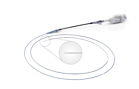
Intravascular ultrasound (IVUS) technology provides critical real-time cross-sectional imaging of coronary arteries and peripheral vascular lesions. By delivering a miniature ultrasound catheter into the target vessel, physicians can accurately evaluate lumen geometry, plaque morphology, and stent expansion conditions. Compared with conventional angiography, IVUS offers significantly higher diagnostic resolution and enables a more detailed assessment of vascular structures.
The quality of high-frequency ultrasound imaging depends heavily on the integrity of electrical signal transmission between the distal transducer and the proximal signal processing system. As modern IVUS transducers continue to increase their operating frequency range, typically reaching 40 MHz to 60 MHz to achieve axial resolutions below 100 microns, the internal electrical interconnection within the catheter has become one of the critical factors limiting overall system performance.
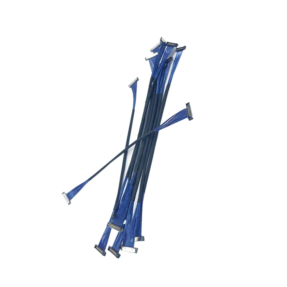
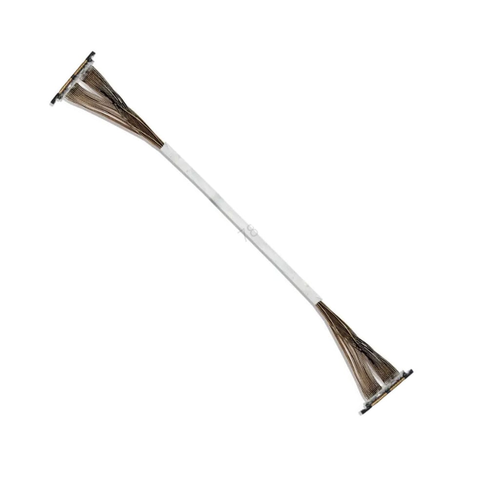
Ultra-fine micro coaxial cable assemblies are increasingly adopted in advanced IVUS catheter designs because they provide the combination of miniature size, controlled impedance, low signal loss, EMI shielding, and mechanical reliability required for high-resolution intravascular imaging.
IVUS catheter designs impose a combination of extreme space constraints, high-frequency signal transmission requirements, controlled impedance, EMI protection, and repeated mechanical movement.
An ultra-fine micro coaxial cable assembly addresses these requirements by integrating a controlled transmission path into a very small physical structure.
The key engineering relationship is:
Catheter Space → Cable Diameter → Channel Density → Impedance / Capacitance → Signal Loss → Shielding → Mechanical Reliability
If → the catheter has very limited internal routing space
Then → reduce cable dimensions only while maintaining the required electrical and mechanical performance
Why → reducing cable size alone does not guarantee that the resulting structure will meet the imaging system requirements.
If → the imaging signal operates at high frequency
Then → evaluate conductor loss, dielectric loss, impedance continuity and finished-cable attenuation
Why → high-frequency transmission performance depends on the complete transmission structure.
If → multiple channels must be routed through the catheter
Then → evaluate channel density, cable OD, individual shielding and electrical consistency together
Why → increasing channel count can create both mechanical and signal-integrity constraints.
If → the cable experiences bending, torque or push-pull movement
Then → validate the cable assembly under representative mechanical conditions
Why → conductor fatigue, shield deformation and dielectric movement can affect long-term assembly performance.
The current HOTTEN article describes IVUS catheter challenges including limited internal space, high-frequency transmission, impedance matching, EMI shielding and mechanical fatigue, and identifies ultra-fine micro coaxial assemblies as a way to address these combined requirements.
For customized IVUS Cable, HOTTEN currently provides dedicated IVUS cable configurations including high-resolution imaging wire and single-use IVUS wire solutions.
1. Extremely Limited Space Inside the Catheter
IVUS catheters typically have an outer diameter of only 2.5 Fr to 3.5 Fr (0.83–1.17 mm). Within this confined space, engineers must accommodate guidewire lumens, mechanical drive shafts or ASIC interconnections, flushing channels, and electrical wiring. The remaining space for cable routing is often only a fraction of a millimeter.
2. High-Frequency Signal Transmission and Loss Control
Operating frequencies between 20 MHz and 60 MHz expose conventional conductors to skin effect, dielectric loss, and EMI. Excessive attenuation degrades signal-to-noise ratio (SNR), leading to image noise, reduced penetration depth, and blurred vessel boundaries.
3. Precise Impedance Matching
Piezoelectric transducers and array ICs require a stable characteristic impedance, typically 50Ω or 75Ω. Impedance discontinuities generate standing waves, ringing, and image artifacts. Maintaining uniform impedance in an ultra-fine, continuously flexing cable is a significant engineering challenge.
4. Electromagnetic Interference (EMI) Shielding Requirements
Catheterization laboratories contain numerous EMI sources, including fluoroscopy systems, patient monitors, and electrosurgical generators. In multimodal catheters such as IVUS-OCT and IVUS-FFR, effective shielding is also essential to suppress crosstalk between high-speed digital channels and sensitive analog signals.
5. Mechanical Flexibility and Fatigue Reliability
The cable assembly must tolerate repeated bending, torque transmission, and push-pull forces while preventing dielectric deformation, shield damage, and conductor fatigue.
• Ultra-Small Cable Diameter (0.15–0.25 mm, AWG50–AWG44) enables high-density integration within miniature catheter shafts.
• Stable High-Frequency Performance: Silver-plated copper alloy conductors combined with low-dielectric PFA insulation minimize insertion loss and phase distortion over cable lengths of 1.5–2.0 m.
• Highly Controlled Characteristic Impedance: Symmetrical coaxial geometry maintains impedance within approximately ±2 Ω to ±3 Ω at 50 MHz, minimizing signal reflections.
• Near-Complete EMI Shielding: High-density braided or served shields provide nearly 100% shielding coverage, improving dynamic range and image stability.
• Outstanding Mechanical Flexibility: High-strength alloy conductors and low-friction fluoropolymer jackets deliver excellent fatigue resistance and smooth movement within the catheter.
• AWG50–AWG40 conductor options with solid or stranded alloy constructions.
• Single micro coaxial cables for rotational IVUS systems.
• Multi-coaxial bundles for 16-, 32-, or 64-channel phased-array IVUS catheters.
• Precision micro-termination using resistance micro-welding, conductive adhesive bonding, and automated laser stripping, supporting FPCs, transducer PCBs, and miniature circular connectors with pitches down to 0.20 mm.
For an OEM IVUS project, cable selection should start with the catheter architecture and imaging requirements, then work backward into cable dimensions and construction.
A practical selection sequence is:
Catheter Envelope → Frequency → Signal Requirements → Channel Count → Cable OD → Impedance / Capacitance → Shielding → Flexibility → Termination → Validation
The smallest available cable is not automatically the correct cable.
The design has to satisfy the electrical, mechanical and integration requirements simultaneously.
The first design constraint is often physical space.
The current HOTTEN article describes IVUS catheter outer diameters in the range of 2.5 Fr to 3.5 Fr, with space also needed for guidewire lumens, drive shafts, flushing channels and other internal structures.
For OEM engineering, the relevant question is therefore:
How much space can actually be allocated to the cable structure?
If → only a fraction of a millimeter is available for cable routing
Then → define the maximum cable OD before selecting conductor and shielding structures
Why → cable diameter becomes a system-level mechanical constraint.
If → channel count increases inside the same catheter envelope
Then → evaluate high-density micro coaxial or bundled coaxial architectures
Why → cable architecture may determine whether the required number of signal paths can physically fit.
The conductor size should be selected in the context of the electrical requirement.
The current HOTTEN IVUS article discusses operating frequencies around 20–60 MHz and notes that higher-frequency operation introduces conductor, dielectric and EMI considerations.
Relevant parameters can include:
| Parameter | Engineering Question |
|---|---|
| Frequency | What frequency range must be transmitted? |
| Signal Type | RF / imaging / analog / other? |
| Impedance | 50Ω / 75Ω / other? |
| Attenuation | What signal loss is acceptable? |
| Capacitance | Is the cable capacitance constrained? |
| Cable Length | What is the complete signal-path length? |
| Channel Count | How many signal paths are required? |
If → the application requires very small cable dimensions
Then → compare conductor size against attenuation, resistance, flexibility and manufacturing requirements
Why → a smaller conductor may improve packaging while creating additional electrical or manufacturing constraints.
The current HOTTEN solution range lists AWG50–AWG40 conductor options for customized medical micro coaxial structures.
For IVUS systems, the engineering objective is not simply minimum cable diameter.
The relevant trade-off is:
Smaller OD
vs.
Electrical Performance
vs.
Mechanical Reliability
vs.
Manufacturability
If → a smaller conductor is needed to fit the catheter
Then → evaluate its effect on attenuation, resistance, flexibility and termination feasibility
Why → the conductor is one part of the complete cable architecture.
If → the smallest cable construction is difficult to terminate consistently
Then → evaluate a slightly different conductor, insulation or termination structure
Why → a cable that fits physically but cannot be assembled repeatably may not be suitable for production.
This is an important distinction for OEMs evaluating ultra-fine cable suppliers.
For IVUS, the impedance requirement does not stop at the cable itself.
The signal path may be:
Transducer
→ Micro Coaxial Cable
→ Micro-Termination
→ FPC / PCB
→ Connector / Interface
→ Imaging Electronics
If → the raw micro coaxial cable meets the target impedance
Then → verify the finished transition into the transducer and electronics
Why → local discontinuities can occur at the cable ends.
The current HOTTEN article identifies 50Ω or 75Ω as typical impedance requirements in IVUS signal paths and links impedance discontinuity with reflections and potential image artifacts.
For additional impedance-control engineering:
What Is Cable Impedance and Why Does It Matter in High Frequency Cable Assemblies?
For an ultra-fine medical coaxial cable, impedance and capacitance should not necessarily be treated as isolated specifications.
Cable capacitance can depend on:
If → the IVUS transducer or receiving electronics are sensitive to cable capacitance
Then → include capacitance in the initial cable specification
Why → changing conductor or dielectric geometry can affect multiple electrical characteristics simultaneously.
If → the design requires multiple matched channels
Then → consider channel-to-channel capacitance consistency
Why → differences between channels can create variation in signal behavior.
This links directly to the broader HOTTEN Micro-Coax engineering article:
How Micro Coaxial Cable Design Ensures Signal Integrity in Medical Devices
IVUS systems can use either individual or multi-channel micro coaxial arrangements.
The current HOTTEN article describes:
For OEM design:
If → multiple analog channels are densely routed
Then → evaluate individual-channel shielding and overall shielding
Why → channel-to-channel coupling and external EMI are separate interference mechanisms.
If → shielding is increased without considering cable OD
Then → verify whether the resulting structure still fits the catheter envelope
Why → shielding consumes physical space and can affect cable flexibility.
This creates a direct link to:
How Low-Noise Medical Cable Assemblies Support More Accurate Diagnostic Signals
One of the important differences between a normal coaxial cable and an IVUS micro coaxial assembly is the scale of the termination.
The current HOTTEN article describes micro-termination using:
For OEM engineers:
If → the cable uses an ultra-fine conductor
Then → define the termination method together with the connector or PCB interface
Why → termination feasibility can become the limiting factor even when the cable itself is technically suitable.
If → the connector pitch is extremely small
Then → evaluate conductor preparation, positioning, soldering/welding/bonding and inspection capability as part of supplier qualification
Why → assembly precision becomes a critical production variable.
An IVUS cable may be exposed to:
If → the cable is continuously exposed to mechanical movement
Then → select conductor, dielectric, shield and jacket structures together
Why → changing one component can affect both flexibility and electrical stability.
If → the cable is mechanically deformed during operation
Then → evaluate electrical performance before and after representative mechanical testing
Why → mechanical survival alone does not prove signal-integrity stability.
This connects directly to:
How Flex-Life Testing Helps Medical Cable Assemblies Maintain Performance After Repeated Bending
Not every IVUS system needs the same cable structure.
If → the system uses a rotational imaging architecture
Then → evaluate a compact single or limited-channel micro coaxial structure together with mechanical rotation requirements
Why → mechanical movement can become an important part of the cable design.
The current HOTTEN article specifically lists single micro coaxial cable structures for rotational IVUS systems.
If → the system uses a multi-channel phased-array architecture
Then → evaluate channel count, channel-to-channel consistency, individual shielding, cable OD and termination density together
Why → the electrical and mechanical constraints grow as the number of channels increases.
HOTTEN currently describes 16-, 32- and 64-channel multi-coaxial bundle configurations in its IVUS engineering examples.
The existing HOTTEN article lists:
TDR
→ VNA Insertion Loss / Bandwidth
→ High-Voltage / Insulation Resistance
→ Mechanical Flex-Life Testing
as its main validation methods.
For OEM qualification, this can be extended into:
Initial Electrical Baseline
→ Mechanical Validation
→ Post-Test Electrical Validation
→ Dimensional / Visual Inspection
→ Failure Analysis
If → the cable passes initial RF testing
Then → perform application-representative mechanical validation
Why → initial electrical compliance does not prove stability after mechanical stress.
If → electrical parameters change after flex testing
Then → investigate conductor fatigue, shield deformation, dielectric movement and termination stress
Why → degradation may begin before the assembly develops a complete electrical open circuit.
A useful IVUS cable RFQ should define both catheter integration requirements and electrical performance.
| Category | Recommended Information |
|---|---|
| Application | IVUS / rotational / phased-array / other |
| Catheter OD | Available physical envelope |
| Cable Space | Maximum routing space |
| Frequency | Operating frequency range |
| Impedance | Nominal value |
| Capacitance | Target / maximum |
| Attenuation | Maximum acceptable loss |
| Channel Count | Number of signal paths |
| Conductor | AWG / material / construction |
| Dielectric | Material / structure |
| Cable OD | Maximum allowable diameter |
| Shielding | Individual / overall / other |
| Cable Length | Nominal + tolerance |
| Flexibility | Static / dynamic |
| Torsion | Required rotation if applicable |
| Connector | Part number / interface |
| Termination | Welding / bonding / soldering / other |
| Connector Pitch | Interface dimensional requirement |
| Environmental | Temperature / humidity / other |
| Testing | TDR / VNA / insulation / mechanical |
| Production | Prototype / qualification / mass production |
If → the RFQ only says “ultra-fine IVUS cable”
Then → add catheter envelope, channel count, frequency, impedance, cable OD, termination and mechanical requirements
Why → “ultra-fine” describes size but does not define the electrical or assembly requirements.
A practical OEM design sequence is:
IVUS Architecture
→ Catheter Envelope
→ Signal Frequency
→ Channel Count
→ Impedance / Capacitance
→ Required Loss
→ Conductor Size
→ Dielectric Structure
→ Cable OD
→ Shielding
→ Flexibility / Torsion
→ Termination
→ Electrical Validation
→ Mechanical Validation
→ Production Validation
Rotational Imaging
→ determine available cable space
→ define signal frequency
→ establish impedance
→ determine allowable cable OD
→ select ultra-fine conductor
→ define dielectric structure
→ select shielding
→ evaluate rotation-related mechanical loading
→ define termination
→ perform RF validation
→ perform mechanical testing
→ verify production consistency.
Multi-Channel Array
→ define channel count
→ determine available catheter space
→ establish impedance and capacitance requirements
→ determine cable architecture
→ select conductor size
→ define individual-channel shielding
→ control channel-to-channel consistency
→ define high-density termination
→ test electrical performance
→ perform mechanical validation
→ qualify production.
How Micro Coaxial Cable Design Ensures Signal Integrity in Medical Devices
How High-Frequency Coaxial Cable Supports Cleaner Signals in Advanced Imaging Probes
How Low-Noise Medical Cable Assemblies Support More Accurate Diagnostic Signals
What Is Cable Impedance and Why Does It Matter in High Frequency Cable Assemblies?
How Flex-Life Testing Helps Medical Cable Assemblies Maintain Performance After Repeated Bending
How to Select the Right Foaming Technology for Micro Coaxial Cable Insulation?
How Custom Medical Cables Are Processed and Inspected Before Delivery
Typical validation includes:
• Time Domain Reflectometry (TDR)
• Insertion Loss and Bandwidth Measurement using a Vector Network Analyzer (VNA) from 10 MHz to 100 MHz
• High-Voltage and Insulation Resistance Testing
• Mechanical Flex Life Testing under simulated anatomical bending conditions
High-resolution IVUS imaging depends on reliable transmission of high-frequency electrical signals through extremely confined catheter structures. With their miniature dimensions, tightly controlled impedance, low transmission loss, robust EMI shielding, and exceptional mechanical flexibility, micro coaxial cable assemblies have become a core interconnection technology in modern IVUS catheter design.
As IVUS platforms continue to evolve toward higher frequencies, higher channel counts, and multimodal imaging, partnering with an experienced medical cable assembly manufacturer helps OEMs overcome both signal integrity and mechanical integration challenges while accelerating next-generation cardiovascular device development.
 Hot News
2026-09-17
2026-09-04
2025-12-17
2025-12-11
2025-12-05