 EN
EN
Quick Links

Home > News > Company news
The continued miniaturization of flexible endoscopes and minimally invasive surgical instruments has placed increasingly stringent demands on the available space for imaging systems. In practical system development, the reliability of the image transmission link is just as critical as the performance of the image sensor itself. Dynamic flexing within ultra-small channels, high-density electromagnetic noise, and miniature interconnects collectively create significant engineering challenges for high-speed differential signal transmission between the compact camera module and the main ISP board.
A compact camera module such as the OV9734 can be used where a small image sensor and short signal path are required, but the cable connecting the camera module to the main electronics must be designed around the complete mechanical and electrical interface.
The OV9734 is a compact 1/9-inch CMOS image sensor supporting 1280 × 720 resolution, up to 30 fps, and a 1-lane MIPI output. OmniVision specifies CSP and COB package options, with the sensor designed for compact electronic devices.
For a medical imaging system, the cable assembly therefore needs to address more than simply connecting the sensor. OEM engineers typically need to control cable size, connector geometry, signal transmission, shielding, flex performance, strain relief, and assembly consistency so that the cable fits the imaging module without introducing unnecessary electrical or mechanical risk.
| Design requirement | Cable assembly consideration | Why it matters |
|---|---|---|
| Compact camera module | Micro / ultra-fine cable construction | Reduces space required around the camera |
| MIPI signal interface | Suitable high-speed interconnect structure | Helps maintain signal integrity |
| Small connector area | Fine-pitch connector and controlled termination | Supports compact PCB integration |
| Flexible routing | Small OD and appropriate bending characteristics | Allows the cable to follow the device structure |
| EMI control | Appropriate shielding and termination | Helps reduce unwanted interference |
| Mechanical reliability | Strain relief and controlled cable exit | Protects the camera-side connection |
| OEM integration | Custom length, connector and routing | Matches the actual device architecture |
The key engineering principle is:
The camera module, cable, connector, and host PCB should be considered as one interconnect system rather than as separate components.
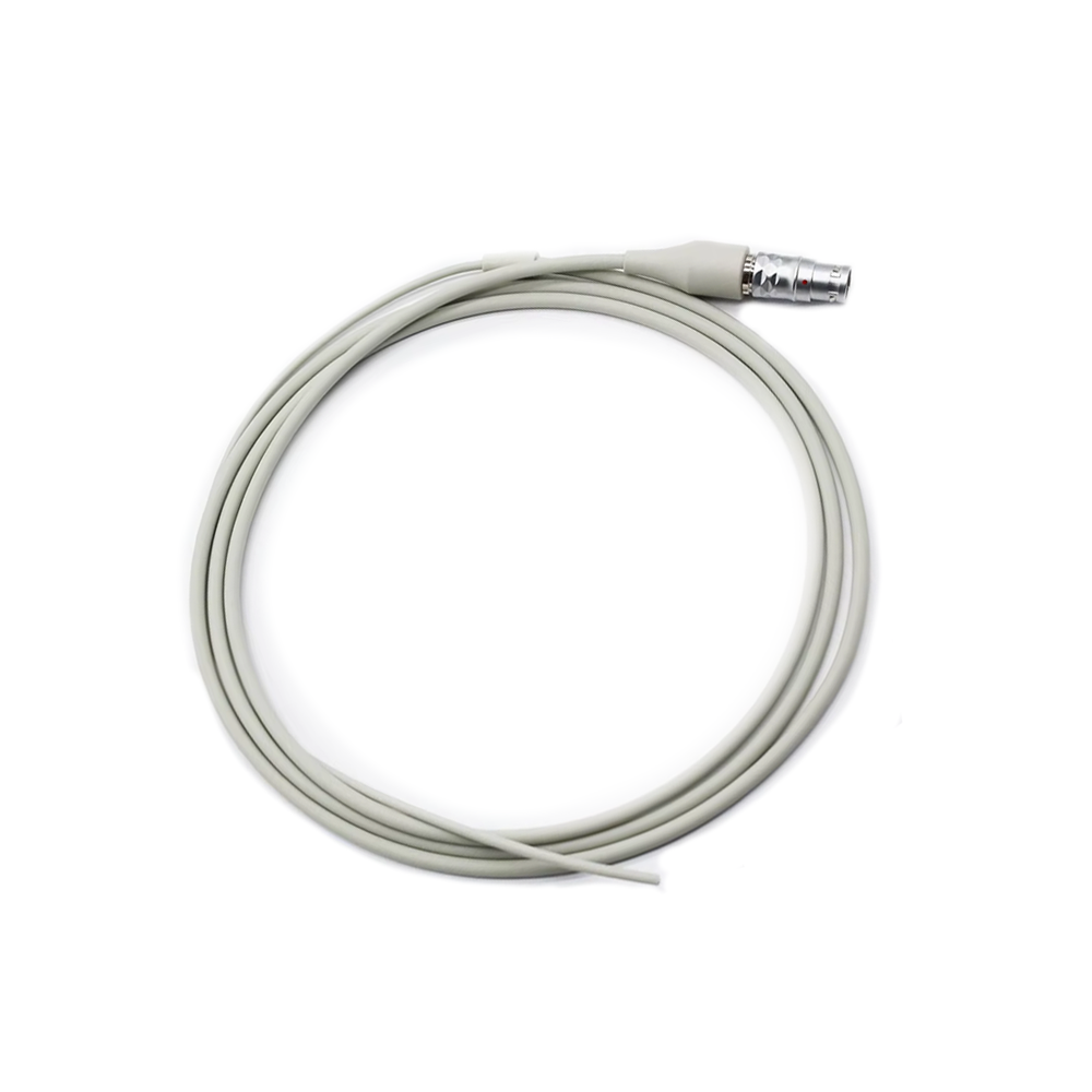
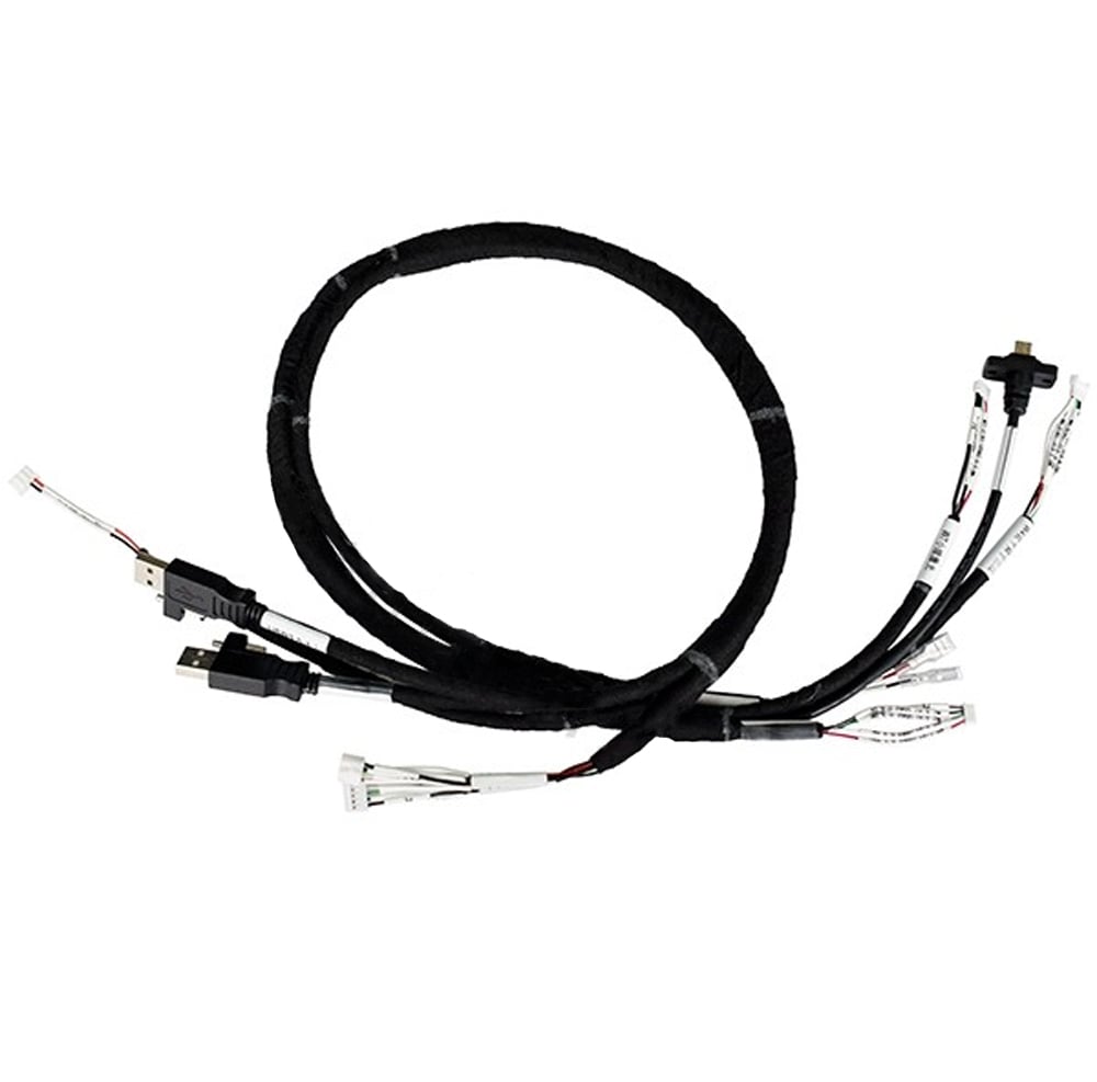
For compact imaging applications, HOTTEN provides Micro Coaxial Cable Assembly and Medical Cable Assembly solutions for customized OEM designs.
The OVM9734 features a Wafer-Level Optics (WLO) package and outputs 720p video through a MIPI CSI-2 interface, making it specifically designed for applications with extremely limited installation space.
Because the front-end camera module is already highly integrated, system designers increasingly focus on the physical performance of the signal transmission path. The high-frequency cable assembly directly influences insertion loss, impedance continuity, and frame integrity during high-speed image transmission between the camera module and the image signal processor (ISP).
1. High-Speed Signal Integrity
The MIPI CSI-2 protocol relies on low-voltage differential signaling (LVDS) to transmit high-speed image data. Miniature coaxial cable assemblies with tightly controlled differential impedance (typically 100 Ω) minimize insertion loss and maintain excellent eye diagram performance.
2. Space Constraints and Dynamic Flex Reliability
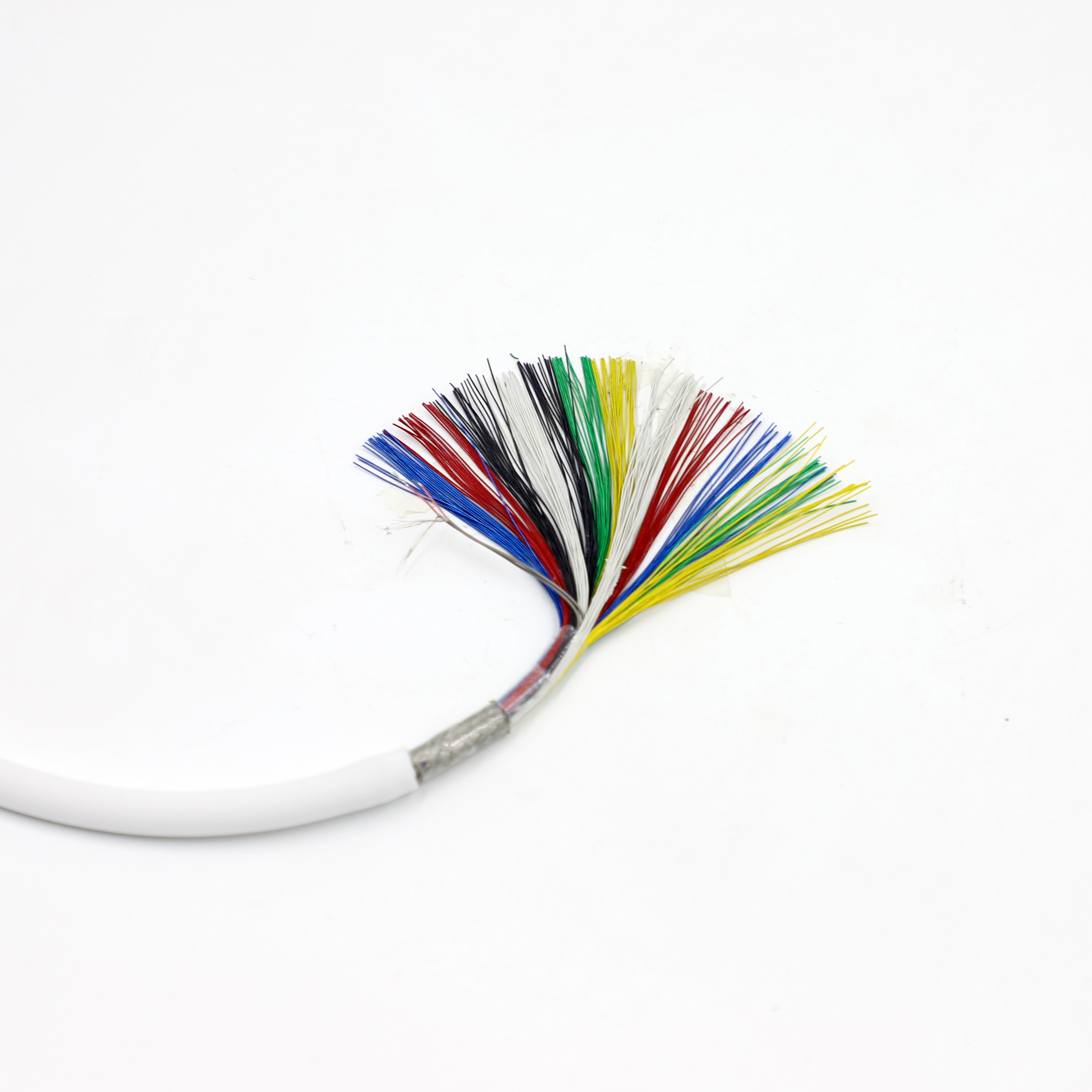
Medical cable assemblies must pass through extremely small channels while providing a small bending radius, excellent flexibility, and resistance to repeated bending and twisting without conductor fatigue or insulation failure.
3. EMI Shielding in High-Density Electromagnetic Environments
Medical environments contain switching power supplies, motors, and surgical equipment that generate EMI. High-density braided or served shields isolate high-speed data channels from external interference and suppress internal crosstalk.
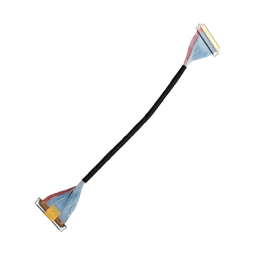
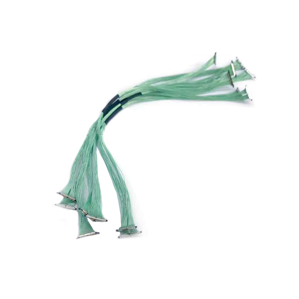
Micro Coaxial Cable Assemblies
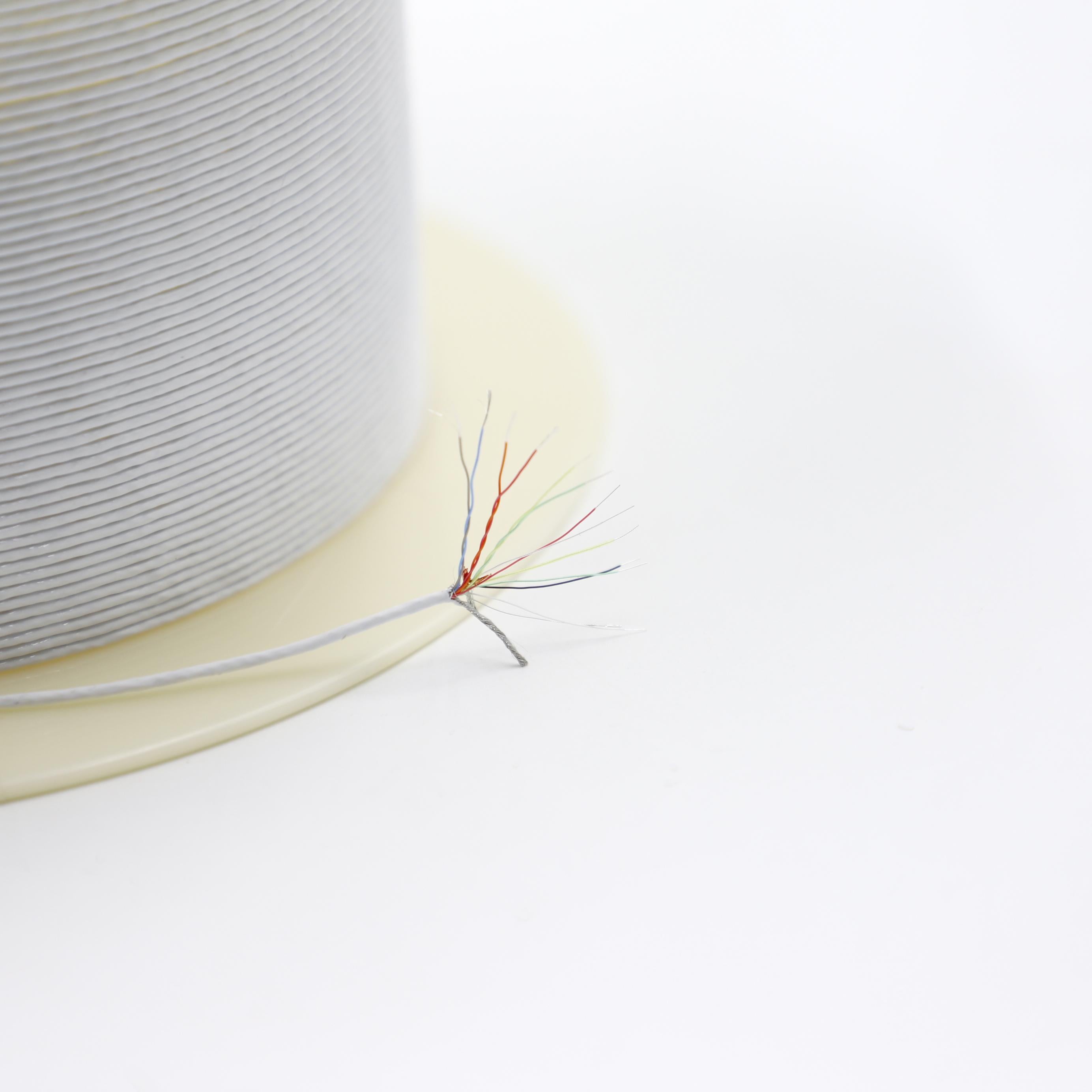
Ultra-fine AWG 36–46 micro coaxial cable assemblies are the preferred solution for medical endoscopes and long-reach imaging probes, providing excellent high-frequency transmission, controlled impedance, and outstanding multi-axis flexibility.
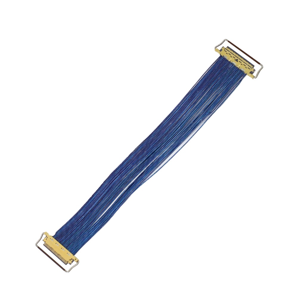
Flexible Printed Circuits (FPC)
FPCs are suitable for short-distance fixed routing inside handles or rigid housings, offering precise conductor geometry and an extremely compact profile.
Customization options include cable length, miniature connector selection, precision wire stripping, and biocompatible jacket materials compatible with sterilization requirements.
• Medical Endoscopy Systems
Used in gastrointestinal, urological, and respiratory endoscopes requiring miniature diameter and excellent torsional flexibility.
• Miniaturized Medical Imaging Devices
Suitable for portable diagnostic equipment, handheld ENT imaging devices, and dental imaging probes requiring stable high-speed image transmission.
• Medical Robotics and Precision Industrial Vision
Designed for surgical robots and precision inspection systems that require long-term vibration resistance and dynamic flex durability.
Hotten provides precision engineering evaluation and cable assembly services including:
• Ultra-fine micro coaxial processing (precision stripping, laser micro-welding, overmolding)
• Broad interface compatibility including MIPI CSI-2 architectures
• Design for Manufacturability (DFM) evaluation based on drawings, CAD models, or samples
• 100% electrical testing including continuity, insulation resistance, and signal integrity verification
The first step is to identify exactly how the camera module communicates with the host electronics.
For the OV9734, OmniVision specifies a MIPI output with 1-lane RAW data, together with control and power interfaces.
This means the cable design should not be selected simply according to physical size.
OEM engineers should confirm:
If the camera uses a high-speed differential interface, then the cable and connector should be evaluated for the complete high-speed path, because the cable transition and connector can contribute to discontinuities even when the cable itself appears mechanically suitable.
Reducing cable diameter is valuable in compact imaging equipment, but simply making a cable thinner is not automatically the correct solution.
A smaller cable changes several engineering parameters simultaneously:
| Parameter | Possible design trade-off |
|---|---|
| Outer diameter | Smaller package vs. mechanical robustness |
| Conductor size | Smaller size vs. electrical resistance |
| Insulation thickness | Smaller OD vs. dielectric control |
| Shielding | Smaller profile vs. EMI performance |
| Bend radius | Better routing vs. mechanical durability |
| Connector size | Smaller interface vs. termination difficulty |
| Cable length | Packaging flexibility vs. signal loss / system margin |
If the imaging module must fit inside a very restricted space, then cable miniaturization should be optimized together with conductor, dielectric, shielding, and connector design, because reducing one dimension in isolation can create problems elsewhere in the interconnect.
This is particularly important when the camera module is mounted close to the optical assembly or inside a small medical instrument.
The cable assembly may interface directly with a compact camera module, PCB, or fine-pitch connector.
At this scale, the termination area can become more difficult to manufacture and inspect.
Engineering considerations include:
If the termination uses a fine-pitch connector, then assembly fixtures and process controls become more important, because small positional errors can affect connector mating, electrical contact, or mechanical reliability.
For OEM projects, the connector manufacturer, exact part number, drawing, and mating information should therefore be included in the RFQ whenever available.
Medical imaging equipment can contain multiple electrical circuits, clocks, motors, displays, power electronics, and wireless or RF subsystems.
The cable assembly can therefore become part of the system-level electromagnetic environment.
Shielding design should consider:
If the camera cable passes close to switching power circuits or other high-noise components, then shielding and routing should be considered together, because cable-level shielding cannot completely compensate for poor system-level routing.
For applications requiring higher-frequency or controlled RF interconnects, HOTTEN also provides RF Coaxial Cable Assembly solutions.
A miniature imaging cable may be routed through a compact enclosure or attached to a moving imaging mechanism.
The cable should therefore be classified according to its actual mechanical condition:
| Application condition | Engineering focus |
|---|---|
| Static installation | Minimum bend radius and strain relief |
| Repeated movement | Flex life and conductor fatigue |
| Rotation / torsion | Torsional performance |
| Tight internal routing | Small OD and controlled bend radius |
| Frequent handling | Jacket durability and termination protection |
| Instrument insertion / withdrawal | Strain relief and connector retention |
If the cable experiences repeated bending near the camera module, then the cable construction and strain relief should be validated under representative movement conditions, because a mechanically compact design still needs to maintain electrical continuity and signal performance throughout its service life.
For OEM medical imaging projects, a generic “camera cable” specification is usually not enough.
A practical engineering package should define:
| RFQ parameter | Information to provide |
|---|---|
| Camera module | Exact model / package |
| Interface | MIPI, analog, LVDS or other interface |
| Connector | Manufacturer and part number |
| Pinout | Signal and power assignment |
| Cable length | Finished length and tolerance |
| Cable OD | Maximum allowable diameter |
| Bend radius | Static and dynamic requirements |
| Shielding | Required construction or performance |
| Termination | Connector / board / camera-side interface |
| Mechanical | Strain relief, routing and exit direction |
| Environment | Temperature, humidity, cleaning or other exposure |
| Testing | Continuity, insulation, signal or mechanical testing |
| Quantity | Prototype, pilot and mass-production volume |
If the camera module is already fixed, then provide the camera drawing or interface dimensions together with the cable requirements, because the available connection space can determine the practical cable construction and termination method.
Cable performance should ultimately be evaluated together with the actual camera module and host electronics.
Depending on the system, prototype validation can include:
| Validation | Engineering purpose |
|---|---|
| Continuity testing | Verify all electrical paths |
| Insulation testing | Check electrical isolation where applicable |
| Signal integrity testing | Verify high-speed transmission |
| Connector retention | Confirm mechanical connection |
| Pull testing | Evaluate termination strength |
| Flex testing | Evaluate repeated movement |
| Dimensional inspection | Verify fit within the device |
| EMC/EMI evaluation | Assess system-level interference behavior |
| Environmental testing | Evaluate performance under defined conditions |
If a prototype passes only a basic continuity test, then that does not by itself demonstrate camera-system performance, because a high-speed imaging interface can be affected by interconnect design even when every conductor is electrically continuous.
For compact medical imaging projects, the supplier's value is not limited to supplying cable materials.
A suitable OEM manufacturing process should connect:
camera interface → cable construction → connector selection → termination → shielding → mechanical protection → testing → production control
The supplier should be able to work from engineering drawings, BOM information, connector specifications, prototype requirements, and defined validation conditions.
If the camera module and cable must be customized together, then an experienced custom cable assembly manufacturer can help reduce integration iterations, because mechanical dimensions, termination, routing, and production processes can be reviewed before mass production.
HOTTEN's Micro Coaxial Cable, Micro Coaxial Cable Assembly, and Medical Cable Assembly capabilities are applicable to compact camera and medical imaging interconnect requirements.
For medical device manufacturers, selecting the appropriate cable assembly solution is just as important as selecting the imaging sensor itself.
A rigorously engineered and fully validated high-frequency cable assembly ensures stable signal transmission, long-term mechanical durability, and consistent diagnostic imaging performance throughout the product lifecycle.
By combining optimized electrical performance with reliable mechanical design, customized cable assemblies help maximize the capabilities of OVM9734 camera modules in advanced medical imaging systems.
 Hot News
2026-09-17
2026-09-04
2025-12-17
2025-12-11
2025-12-05