 EN
EN
Quick Links

Home > News > Company news
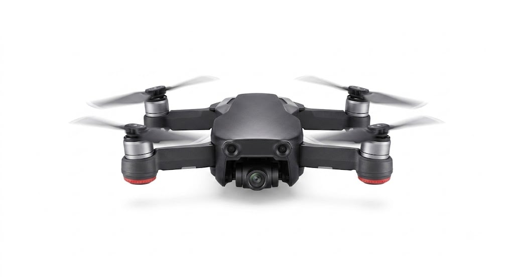
UAV cable assemblies must balance several requirements at the same time because drone systems combine limited internal space, continuous movement, vibration, high-speed data transmission, and strict weight constraints. The appropriate cable construction depends on the routing location and the specific requirements of the camera, gimbal, flight controller, RF module, or other electronic subsystem.
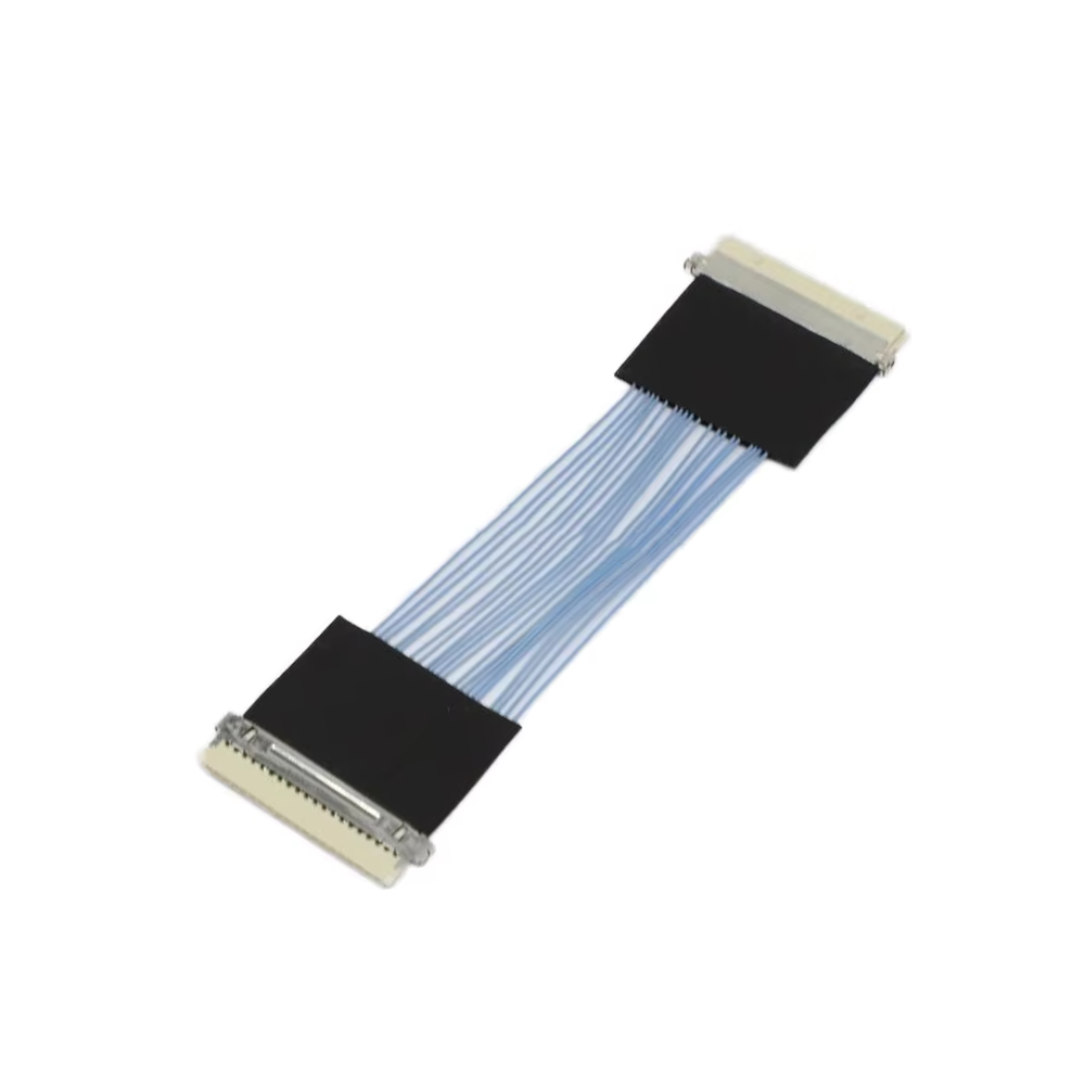
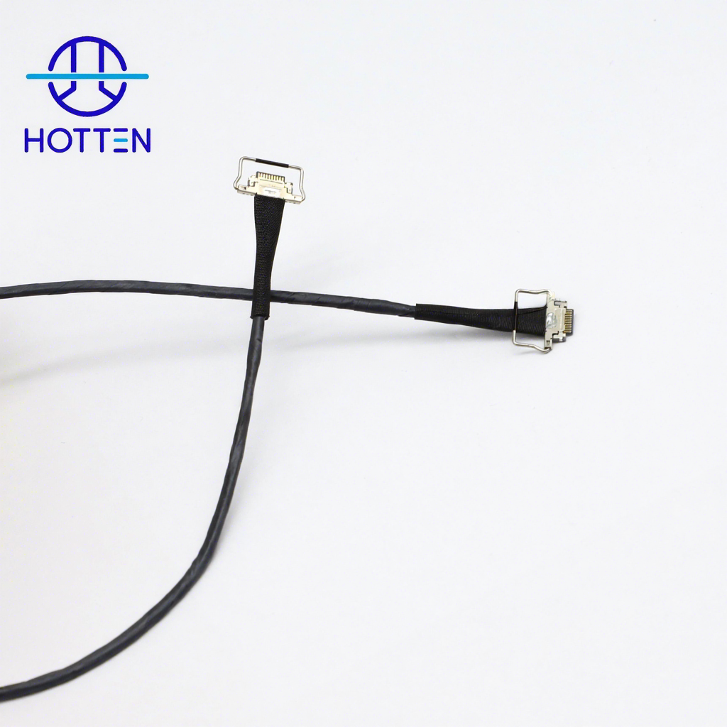
If the cable is installed in a moving gimbal or camera module, engineers should evaluate cable OD, bending performance, flex life, shielding, and signal integrity together. Compact micro-coaxial cable assemblies can be considered when high-speed signals need to pass through a small and continuously moving routing area. See HOTTEN's Gimbal Camera Wire Harness solutions for related applications.
If weight reduction is the main requirement, the complete cable assembly should be evaluated rather than reducing conductor size alone. Conductor material, insulation thickness, shielding structure, jacket construction, cable length, and connector configuration all contribute to the final assembly weight. For conductor-size trade-offs, see How Does AWG Affect Micro Coaxial Cable Performance?.
If the cable is routed close to RF or high-speed electronic modules, shielding, impedance, attenuation, connector transitions, and routing conditions should be considered together. A cable specification should therefore describe the actual electrical and mechanical requirements rather than simply requesting the smallest available cable.
For customized UAV cable assemblies, see HOTTEN's UAV & Robotics Cable Solutions.
In the commercial unmanned aerial vehicle (UAV) industry, the market is experiencing explosive growth in demand for higher-resolution cameras, advanced LiDAR systems, and real-time data processing capabilities. As drones pack more onboard electronics, engineers face a classic engineering dilemma: How to achieve high-speed data transmission without adding deadweight that drains battery life?
More importantly, signal interruption remains a fatal hazard. Within a compact drone chassis, even a minor instance of electromagnetic interference (EMI) or a fragile wire breakage can lead to a catastrophic crash or a total loss of ground telemetry.
To build a highly reliable and lightweight UAV, optimizing core internal cabling is just as critical as upgrading the flight controller. Below, we dive deep into three critical routing zones and examine how advanced micro-coaxial cable manufacturing technologies solve these technical bottlenecks.
Gimbal and Camera Modules (High-Speed Data): UAV gimbals must rotate continuously during flight while enduring constant airframe vibrations. Cabling in this area must support lossless HD video transmission while surviving hundreds of thousands of bending cycles without performance degradation.
Internal Flight Controllers and Board-to-Board Connections: The internal chassis space of a drone is extremely tight. Mainboards, GPS modules, and power distribution systems require ultra-fine, high-density interconnection solutions to save PCB real estate and withstand severe mechanical shocks.
Antenna Transmission (RF Modules): The connectivity between internal radio frequency (RF) modules and antennas demands exceptionally low insertion loss and top-tier EMI shielding performance. This prevents stray signals generated by the drone’s powerful motors from disrupting wireless control signals.
How do you eliminate signal interruptions entirely without wrapping the drone in heavy, bulky shielding? The answer lies in ultra-fine materials science and precise cable structural design.
Fluoropolymer Insulation (FEP/PFA): By utilizing advanced insulation materials like PFA or FEP, micro-fine wires can achieve ultra-thin wall thicknesses while maintaining excellent dielectric properties and high-temperature resistance. This drastically minimizes the total weight of the wire harness.
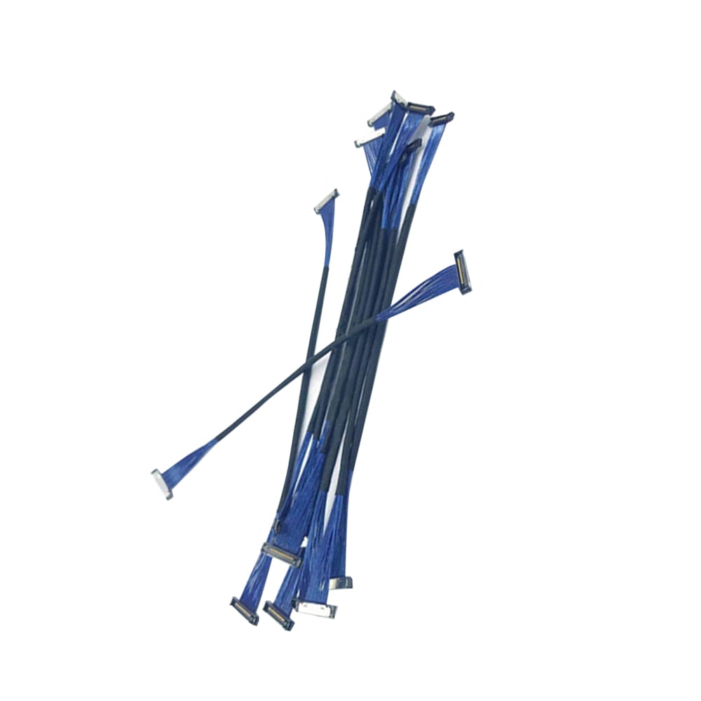
Micro-Coaxial Technology (38 AWG to 50 AWG): For gimbals and high-speed data transmission, micro-coaxial cables offer the ultimate solution. Each ultra-fine line features its own independent shielding layer, ensuring outstanding EMI resistance and zero signal crosstalk within highly congested spaces.
Selecting high-quality bulk wire is the root of ensuring overall system reliability. High-end UAV components have minimal internal spacing, requiring micro-coaxial cables to feature flawless concentricity and extremely tight outer diameter (OD) tolerance controls.
Manufacturing 38 AWG to 50 AWG micro-coaxial cables relies on ultra-high-precision conductor wire drawing, advanced fluoropolymer extrusion processes for ultra-thin walls, and high-density micro-braiding technologies for shielding. This rigorous cable manufacturing process guarantees stable, consistent impedance control and ultimate flexibility, ensuring "lossless signal transmission" under the harshest flight environments.
Selecting a cable for a UAV system is a system-level engineering decision. Weight, signal performance, mechanical movement, EMI protection, and installation space can influence one another, so the cable should be evaluated according to the actual routing zone rather than by a single specification.
If reducing cable weight is the primary objective, engineers should first evaluate the complete cable construction rather than selecting a smaller conductor automatically.
A practical review should consider:
Conductor material and AWG
Insulation thickness and material
Shielding structure
Jacket construction
Cable length
Connector and termination configuration
A finer conductor may reduce conductor size, but the final cable OD and assembly weight also depend on insulation, shielding, jacket, and connector design. See How Does AWG Affect Micro Coaxial Cable Performance? for a detailed discussion of AWG-related trade-offs.
If the cable is routed through a moving gimbal, camera, or robotic mechanism, mechanical flexibility should be evaluated together with signal performance.
The engineering specification should define the actual operating condition, such as:
| Requirement | Parameters to Confirm |
|---|---|
| Compact Routing | Cable OD, core count, minimum space |
| High-Speed Signal | Impedance, attenuation, cable length |
| Repeated Movement | Bend radius, flex cycles, torsion |
| EMI Control | Individual shielding, overall shielding |
| Weight Reduction | Conductor, insulation, shielding, jacket, connector |
| Termination | Connector type, pinout, termination method |
The smallest cable is not automatically the most suitable cable for a moving application. The complete assembly should be evaluated under the expected bending and routing conditions.
If the cable runs near motors, power electronics, RF modules, or other potential interference sources, shielding should be evaluated together with the actual routing environment.
Micro-coaxial constructions can provide individually shielded signal paths, which can be useful for compact high-speed connections. However, connector transitions, termination areas, grounding, and cable routing can also affect system-level EMI performance.
For compact high-density micro-coaxial designs, see HOTTEN's Micro Coaxial Cable Assembly solutions.
Different UAV locations can require different cable priorities.
If the cable is installed in a gimbal or camera module → prioritize flexibility, compact OD, shielding, and high-speed signal performance → then validate flex life and termination reliability.
If the cable connects internal boards or controllers → prioritize compact routing, dimensional consistency, connector integration, and mechanical reliability → then verify the required electrical performance.
If the cable is used for RF transmission → prioritize impedance, attenuation, shielding, connector interface, and cable length → then evaluate the complete RF transmission path.
For application-specific UAV cable development, see Custom UAV Cable Assembly Solutions for Lightweight Industrial Drones.
Before requesting a quotation or prototype, an engineering or procurement team should provide as much of the following information as available:
| RFQ Item | Information to Provide |
|---|---|
| Application | Camera, gimbal, controller, RF, sensor, etc. |
| Cable Type | Micro-coax, electronic wire, harness, or hybrid assembly |
| Conductor | AWG, material, core count |
| Electrical | Impedance, frequency, attenuation, capacitance |
| Mechanical | Length, bend radius, flex cycles, torsion |
| Dimensions | Maximum OD and available routing space |
| Shielding | Shielding structure and required coverage |
| Connector | Manufacturer, part number, pitch, pinout |
| Environment | Temperature, vibration, moisture and other conditions |
| Production | Prototype quantity, annual volume, testing requirements |
Providing drawings, samples, connector part numbers, or existing cable specifications can help the supplier evaluate the complete assembly rather than quoting a generic cable structure.
For broader UAV and robotics requirements, see HOTTEN's UAV & Robotics solutions.
At Hotten, we specialize in the R&D and high-precision manufacturing of ultra-fine micro-coaxial cables. From the stable mass production of highly flexible 48 AWG bare wires to continuously pushing the manufacturing boundaries of 50 AWG processes, we supply the core, premium-quality cable substrates for global drone manufacturers and wire harness assemblers.
Feel free to contact our engineering team anytime to request micro-coaxial cable datasheets and custom samples.
 Hot News
2026-09-17
2026-09-04
2025-12-17
2025-12-11
2025-12-05