 EN
Quick Links

For an OEM cable assembly, meeting the basic electrical specification is only part of the engineering requirement.
A cable can have the correct connector, conductor size and electrical characteristics and still create problems during final device assembly if its physical dimensions are not controlled properly.
Cable length, outer diameter, connector position, pin alignment, bend radius and strain relief dimensions can all affect how the finished cable fits into the customer's equipment.
This is particularly important in compact medical devices, UAV systems, robotics, cameras and other electronics where cable routing space is limited.
The most important cable assembly tolerances are the dimensions that directly affect device fit, connector engagement, cable routing, signal integrity, and mechanical movement.
For OEM projects, these commonly include finished cable length, outer diameter, connector position and orientation, pin alignment, termination position, bend geometry, strain relief dimensions, and branch location.
Not every dimension requires the same tolerance.
If → a dimension directly affects connector mating or device fit
Then → define it as a critical dimension and establish an appropriate tolerance
Why → a small dimensional variation in a critical interface can affect final device integration.
If → a dimension has sufficient installation space or mechanical margin
Then → a wider production tolerance may be acceptable
Why → unnecessary tight tolerances can increase manufacturing difficulty without providing a corresponding system benefit.
If → the cable assembly is installed in a compact medical device, camera, UAV or robotic system
Then → evaluate cable length, OD, connector orientation, bend radius and strain relief together
Why → these dimensions interact with the physical routing path rather than acting independently.
If → the assembly moves repeatedly during operation
Then → define the mechanical transition between the cable, connector and strain relief
Why → the assembly must remain routable and mechanically stable during movement.
For OEM projects requiring customized cable dimensions and connector configurations, see How to Specify a Custom Cable Assembly for OEM Projects.
For complete customized interconnects, see Micro Coaxial Cable Assembly.
 Why Cable Assembly Tolerances Matter
A cable assembly is installed inside a larger mechanical and electrical system. Its dimensions therefore need to work together with the surrounding components.
For example, a small difference in cable length may not matter in an open installation. In a compact enclosure, however, it may affect routing, connector engagement or the position of nearby components.
Common dimensional factors include:
| Parameter | Why It Matters During Integration |
|---|---|
| Finished cable length | Affects routing and connector position |
| Cable outer diameter | Determines available installation space |
| Connector position | Affects mating and assembly orientation |
| Pin alignment | Ensures correct electrical connection |
| Bend radius | Influences routing and mechanical stress |
| Strain relief dimensions | Affects transition between cable and connector |
| Branch position | Determines how a harness fits inside the device |
| Overall assembly dimensions | Affects final mechanical integration |
The required tolerance should therefore be considered as part of the complete cable assembly design rather than treated as a simple production detail.
Finished cable length is one of the easiest specifications to understand, but it can also create practical integration problems.
Consider a cable installed between two fixed connectors.
If the finished length is too short, the cable may be forced into an excessive bend or place mechanical stress on the connector.
If it is too long, the additional cable may interfere with other components or require unnecessary routing space.
For flexible cable assemblies, the specified length should therefore be considered together with:
Connector position
Routing direction
Bend radius
Strain relief
Installation space
Movement requirements
For complex assemblies, OEM drawings should clearly identify the reference points used for measuring finished length.
Cable diameter becomes particularly important when multiple cables are routed through a small enclosure.
A few individual cables may fit easily, while a larger bundle can quickly consume the available routing space.
This is one reason micro coaxial cables and fine electronic wires are useful in high-density applications. Their compact construction can provide more flexibility in cable routing where space is limited.
However, reducing cable diameter should not be treated as an isolated objective.
A smaller cable may affect mechanical strength, shielding structure, electrical performance or manufacturing complexity depending on the design.
The practical target is not simply:
Make the cable smaller.
It is:
Achieve the required dimensions while maintaining the electrical, mechanical and manufacturing requirements of the application.
Connector selection is only one part of cable assembly integration.
The position and orientation of the connector can be equally important.
For example, an OEM may specify:
Connector type
Pin count
Pin assignment
Connector orientation
Exit direction
Cable length
Distance from connector to bend point
Strain relief dimensions
If these details are not clearly defined, two assemblies using the same connector may still behave differently during installation.
This becomes particularly important for high-density connectors and miniature cable assemblies.
A cable assembly may technically use the correct connector but still be difficult to install if the connector exits in the wrong direction or the cable begins bending too close to the interface.
In multi-core and micro coaxial cable assemblies, termination becomes increasingly important as the number of channels increases.
The assembly must not only contain the correct number of conductors. The conductors also need to reach the correct termination positions.
Depending on the application, the manufacturing drawing may need to define:
Pin assignment
Wire sequence
Connector orientation
Termination position
Exposed conductor length
Solder or crimp requirements
PCB termination location
For space-constrained electronics, these details can determine whether the cable assembly can actually be installed into the finished product.
A cable's flexibility is not determined only by the cable itself.
The connector, strain relief and termination area can create a transition from a relatively rigid section to a flexible cable.
If the transition is not considered during design, the cable may be difficult to route even when the cable itself is flexible.
This is especially relevant for applications involving:
Medical probes
Endoscopes
Camera modules
Drone gimbals
Robotics
Compact electronic equipment
The OEM should therefore evaluate the complete assembly rather than judging flexibility from the bulk cable specification alone.
Another issue that can be overlooked is tolerance stack-up.
A finished cable assembly may contain several dimensional requirements at the same time:
Cable length + connector position + termination position + strain relief + bend geometry
Each individual dimension may be within its specified tolerance, while the combined result can still affect the final installation.
For this reason, critical dimensions should be identified during the engineering stage.
Not every dimension needs the same tolerance.
A dimension that directly determines connector engagement may require tighter control than a dimension with more available installation space.
This approach helps avoid unnecessary manufacturing cost while protecting the dimensions that actually matter to the device.
A practical cable assembly drawing should distinguish between general dimensions and critical dimensions.
For example:
| Design Area | Information to Define |
|---|---|
| Cable length | Nominal length and acceptable tolerance |
| Cable OD | Maximum or nominal diameter |
| Connector | Part number and mating interface |
| Connector orientation | Required orientation or exit direction |
| Pinout | Pin assignment and wire sequence |
| Termination | Solder, crimp, PCB or other method |
| Bend area | Minimum bend radius or routing requirement |
| Strain relief | Length, diameter and geometry |
| Branching | Branch position and direction |
| Environmental requirements | Temperature, chemicals, vibration or movement |
This gives the manufacturer a clearer understanding of which dimensions are critical to the final product.
There is no single cable assembly tolerance that is suitable for every application.
A cable used inside a spacious industrial enclosure may have different dimensional requirements from a micro coaxial assembly installed inside a miniature camera module.
Similarly, a stationary cable may have different mechanical requirements from a cable used in a robotic joint or UAV gimbal.
The correct approach is to connect each tolerance to a real engineering requirement.
For example:
Medical imaging probe
Focus may include compact dimensions, connector position, flexibility and repeated movement.
UAV camera
Focus may include lightweight construction, compact routing, connector orientation and vibration-related mechanical requirements.
High-speed electronic module
Focus may include connector alignment, controlled cable geometry and reliable signal transmission.
Robotics
Focus may include routing space, bend radius, repeated movement and strain relief.
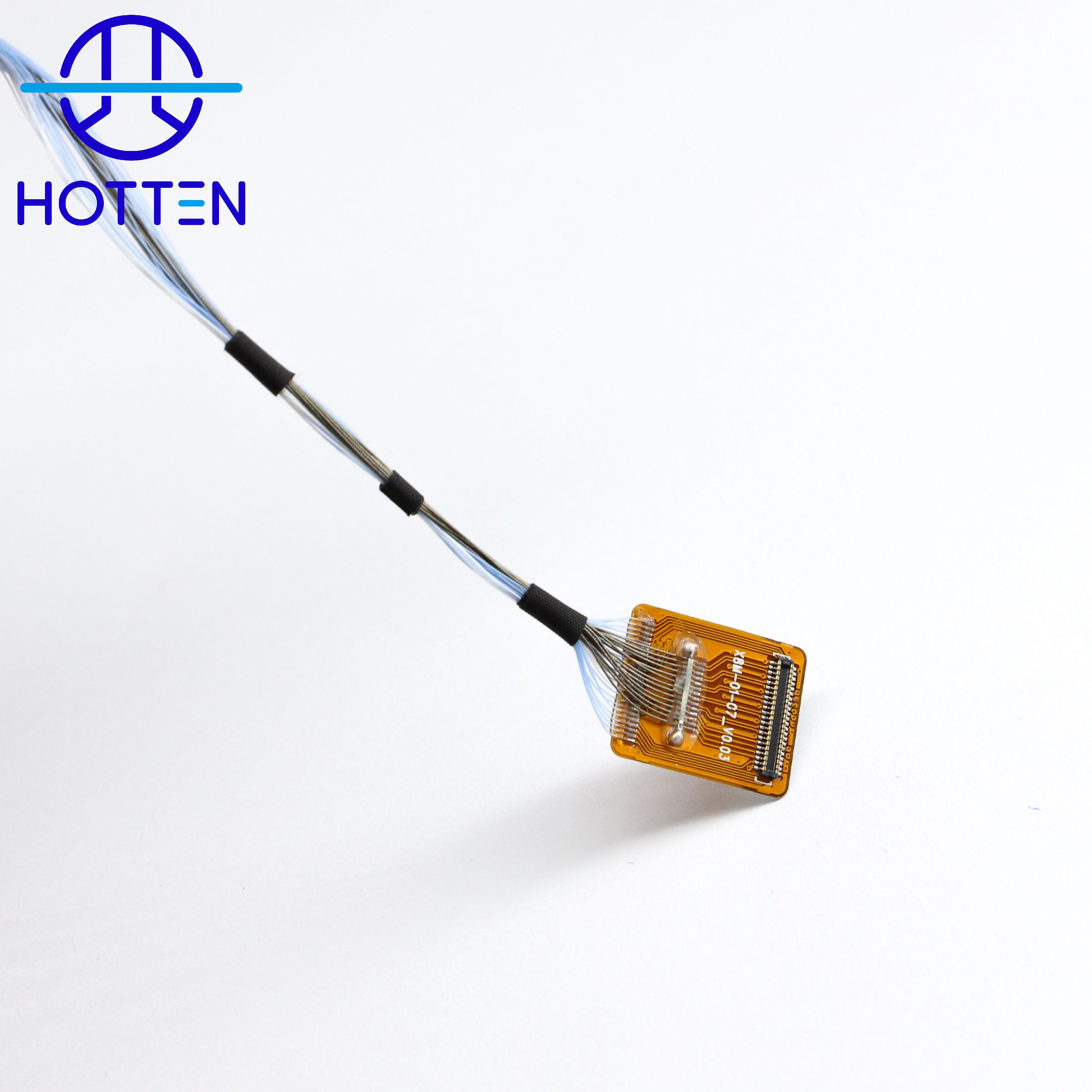 How Should OEM Engineers Define Critical Tolerances for a Custom Cable Assembly?
A useful cable assembly specification should not simply assign the tightest possible tolerance to every dimension.
Instead, engineers should identify which dimensions actually affect the final device and then match the tolerance to the functional requirement and available mechanical margin.
A cable drawing can contain many dimensions, but only some of them may directly affect the finished product.
Typical critical dimensions include:
| Dimension | Potential Integration Impact |
|---|---|
| Finished cable length | Routing and connector engagement |
| Cable OD | Available installation space |
| Connector position | Mating location |
| Connector orientation | Installation direction |
| Pin alignment | Electrical interface |
| Termination position | PCB or connector integration |
| Bend area | Routing and mechanical stress |
| Strain relief | Cable-to-connector transition |
| Branch position | Harness routing |
| Overall assembly envelope | Final mechanical fit |
If → the dimension determines whether the assembly can physically fit
Then → treat it as a critical integration dimension
Why → the production tolerance needs to protect a real device-level requirement.
If → the dimension does not affect fit, function or reliability within the available margin
Then → avoid unnecessarily tight tolerances
Why → tolerance should be driven by function rather than by the desire for maximum dimensional precision.
A common mistake is to inspect each dimension independently.
In an actual cable assembly, several dimensions can combine:
Cable Length + Connector Position + Termination Position + Strain Relief + Bend Geometry
Each individual value may be within specification, while their combined variation still affects the final installation.
If → several tolerances contribute to the same mechanical interface
Then → perform a tolerance stack-up review
Why → the worst-case or combined variation may be more important than any single tolerance.
For example, if a connector must reach a fixed PCB position inside a compact device, the relevant engineering question is not simply:
Is the cable length within tolerance?
It is:
Does the complete cable assembly still reach the required connector position after all relevant dimensional variations are considered?
This is why the cable drawing should be reviewed as a complete assembly rather than as a list of independent dimensions.
OEM engineers often focus first on finished cable length.
However, connector position and orientation can be equally important.
If → the connector must mate with a fixed PCB, socket or device interface
Then → define connector position and orientation clearly
Why → the correct cable length alone does not guarantee correct mating geometry.
The drawing may need to specify:
For miniature and high-density assemblies, these details become increasingly important because there may be very little room to compensate during final installation.
HOTTEN's custom cable assembly development process includes application review, connector configuration and engineering evaluation based on customer requirements. See How to Specify a Custom Cable Assembly for OEM Projects.
Cable OD should not be specified simply as:
“Make the cable as small as possible.”
Instead, define:
Available Space → Maximum Cable OD → Minimum Bend Area → Number of Cables → Routing Path
If → the installation space is highly constrained
Then → specify the maximum allowable cable OD and routing envelope
Why → the actual integration problem is usually available space, not cable diameter by itself.
This is particularly relevant to micro coaxial cable assemblies, compact medical devices, camera modules and other high-density electronic systems.
For compact signal connections, see Micro Coaxial Cable Assembly.
The cable itself may be flexible, but the finished assembly also includes the connector and strain relief.
This creates a transition:
Connector → Strain Relief → Cable → Routing Path
If → the cable immediately bends after the connector
Then → define the required bend geometry and strain-relief dimensions
Why → the transition area may determine how the complete assembly can be installed.
If → the cable is used in a moving application
Then → include movement and repeated-bending requirements in the drawing
Why → static cable flexibility does not necessarily describe the behavior of the finished assembly during operation.
For medical probes, endoscopes, UAV gimbals and robotics, the complete assembly should therefore be evaluated rather than the bare cable alone.
See HOTTEN's Medical Cable Assembly and UAV & Robotics solutions.
Cable assembly tolerances are not only mechanical.
For high-frequency and high-speed applications, changes in physical geometry can also influence the electrical characteristics of the transmission structure.
Relevant parameters may include:
If → the assembly carries controlled high-frequency signals
Then → evaluate dimensional control together with electrical performance
Why → the physical cable geometry forms part of the transmission path.
For RF and controlled-impedance applications, see RF Cable.
A good OEM specification should distinguish between:
Critical Dimension
and
General Dimension
For example:
| Design Area | Possible Approach |
|---|---|
| Connector mating position | Tighter functional tolerance |
| Pin alignment | Tighter control where interface requires it |
| Overall cable length | Based on actual routing requirement |
| Cable OD | Based on available installation space |
| Strain relief | Based on mechanical transition |
| Branch position | Based on routing requirement |
| Non-critical cosmetic dimensions | May allow wider tolerance |
If → a tight tolerance directly protects device fit or function
Then → define and control it carefully
Why → the additional process effort has a clear engineering purpose.
If → a tight tolerance has no functional benefit
Then → reconsider whether it is necessary
Why → excessive tolerance requirements can make production more difficult without improving device performance.
A prototype can sometimes be produced with additional manual adjustment.
Mass production requires a repeatable process.
If → a prototype meets the dimensional requirement only through manual adjustment
Then → evaluate the process before approving the design for volume production
Why → manual correction may not provide the same consistency at production volume.
If → the critical dimensions can be controlled through fixtures, work instructions, inspection and repeatable assembly processes
Then → continue production validation
Why → the manufacturing process has a defined method for maintaining the required dimensions.
HOTTEN's current OEM cable-assembly approach supports development from application review and prototyping through testing and production. (How to Specify a Custom Cable Assembly for OEM Projects)
A practical drawing or RFQ package should identify the dimensions that matter to final device integration.
| Category | Recommended Information |
|---|---|
| Cable length | Nominal length + tolerance |
| Measurement reference | Clearly defined reference points |
| Cable OD | Nominal / maximum allowable OD |
| Connector | Manufacturer + part number |
| Connector orientation | Drawing or defined orientation |
| Pinout | Pin assignment and sequence |
| Termination | Solder / crimp / PCB / other |
| Termination position | Required location |
| Bend area | Bend radius or routing requirement |
| Strain relief | Length / diameter / geometry |
| Branching | Position and direction |
| Electrical requirements | Impedance / frequency / attenuation / etc. |
| Environmental requirements | Temperature / vibration / chemicals / movement |
| Inspection | Critical dimensional and electrical checks |
| Production | Prototype / pilot / annual quantity |
For OEM engineers who do not yet have every cable specification finalized, application information, drawings, connector details and installation constraints can provide a useful starting point for supplier engineering review. HOTTEN describes this type of drawing-, sample- and application-based development for customized cable solutions. (How to Specify a Custom Cable Assembly for OEM Projects)
A useful process is:
Device Interface → Installation Space → Critical Dimensions → Tolerance Stack-Up → Cable Structure → Connector & Termination → Prototype → Validation → Production Control
For example:
Compact medical imaging device
→ define connector locations
→ define routing envelope
→ determine maximum cable OD
→ define finished cable length
→ define bend and strain-relief requirements
→ define termination position
→ identify critical tolerances
→ build prototype
→ check device integration
→ validate production process.
For a UAV camera or gimbal:
Movement → Routing Space → Cable OD → Connector Orientation → Bend Requirement → Strain Relief → Signal Requirement → Prototype → Flex / Vibration Validation
For a high-speed electronic module:
Interface → Connector Position → Cable Geometry → Impedance → Length → Termination → Dimensional Validation → Electrical Validation
The important point is that the tolerance specification should follow the actual application.
这篇文章建议重点链接下面几个页面:
How to Specify a Custom Cable Assembly for OEM Projects
How Micro Coaxial Cable Assemblies Support High-Density Camera and Imaging Systems
How to Balance Mechanical and Electrical Performance in Ultra-Fine Coaxial Cables
Changing a cable assembly after the prototype has already been built can create unnecessary development work.
A dimensional problem discovered during final device integration may require:
Cable redesign
New tooling or fixtures
New samples
Additional testing
Revalidation
Production schedule changes
An early engineering review can identify many of these issues before the first production sample.
The manufacturer can review the drawing together with the application and determine which dimensions are practical, which requirements may conflict, and which specifications should receive tighter process control.
Dimensional consistency becomes even more important when an OEM project moves from prototypes to volume production.
A prototype may be produced with additional manual adjustment. Production requires a repeatable process.
The manufacturing process therefore needs to control the dimensions that directly influence final assembly.
Depending on the project, this may involve:
Defined work instructions
Assembly fixtures
Connector positioning controls
Dimensional inspection
Electrical testing
First article inspection
Production sampling
Process documentation
The exact inspection plan should be based on the cable structure and customer requirements.
Before placing an order, OEM engineers and procurement teams can ask:
The supplier should be able to identify the important dimensional characteristics of the assembly.
The measurement reference points should be clearly defined.
This is particularly important when the assembly has a fixed installation direction.
For high-density assemblies, termination accuracy can directly affect device integration.
An engineering review can identify potential manufacturing or integration problems before samples are produced.
The answer should involve a repeatable manufacturing and inspection process rather than relying only on manual adjustment.
For OEM projects, supplier evaluation should go beyond the ability to manufacture the cable itself.
A suitable supplier should understand the relationship between:
Cable Structure → Connector → Assembly Dimensions → Device Integration → Production Process
This is particularly important for custom micro coaxial cable assemblies, medical cables, UAV cable harnesses, robotics cables and other space-constrained interconnects.
A supplier that can review drawings, discuss application requirements and manufacture the complete assembly can help reduce the gap between an engineering concept and a production-ready cable.
HOTTEN provides customized cable solutions for OEM applications including micro coaxial cable assemblies, medical cable assemblies, UAV and drone cable assemblies, robotics wire harnesses, RF coaxial cable assemblies and fine electronic wires.
Depending on the project, cable structure, dimensions, connector configuration, pin assignment, shielding, cable length and assembly requirements can be customized according to customer drawings, samples and application requirements.
HOTTEN supports the development process from engineering review and prototype samples through testing and volume production.
For OEM projects where cable dimensions are critical to final device integration, customers can provide drawings, samples, connector information and installation requirements for engineering evaluation.
Cable assembly tolerance is the acceptable dimensional or manufacturing variation around a specified requirement, such as cable length, outer diameter, connector position or termination location.
Cable length affects routing, connector engagement and mechanical stress. The importance of the tolerance depends on the installation environment.
Yes. Cable diameter can influence routing space, bundle size, bend radius and the ability to fit the assembly into a compact enclosure.
Yes. When connector orientation affects installation, it should be clearly defined in the engineering drawing.
Yes. Critical dimensions can be defined according to the requirements of the OEM application and the capabilities of the manufacturing process.
Useful information includes drawings, cable length, connector part numbers, pinout, cable structure, electrical requirements, mechanical constraints, environmental conditions, expected quantity and application information.
A cable assembly is part of the mechanical and electrical architecture of an OEM product.
For this reason, dimensional tolerances should not be treated as minor manufacturing details.
Cable length, outer diameter, connector position, pin alignment, bend geometry and strain relief can all affect whether a finished assembly fits the customer's device as intended.
Defining the critical dimensions early and reviewing them with the cable manufacturer can make the transition from prototype to production more predictable.
For OEM customers developing compact medical, UAV, robotics, imaging or advanced electronic equipment, HOTTEN can support customized cable assembly development based on application requirements, drawings and samples.
 Hot News
2026-09-17
2026-09-04
2025-12-17
2025-12-11
2025-12-05