 EN
Quick Links

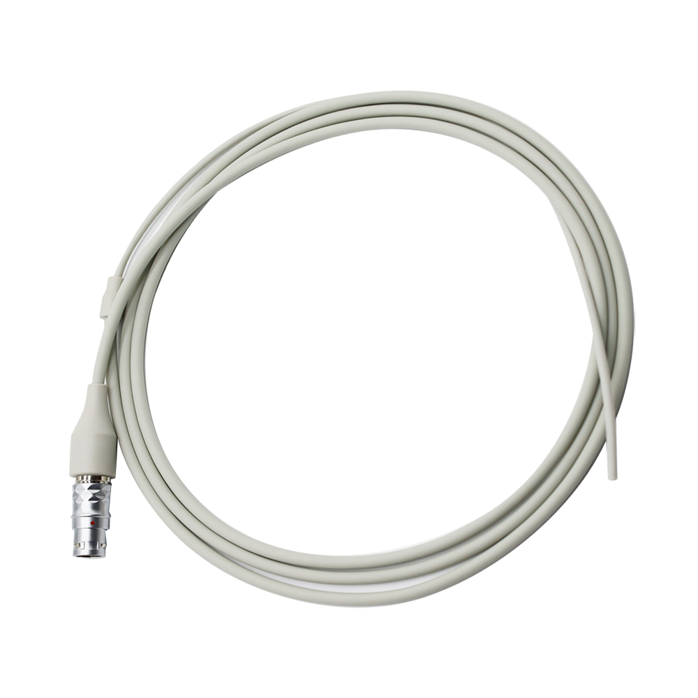
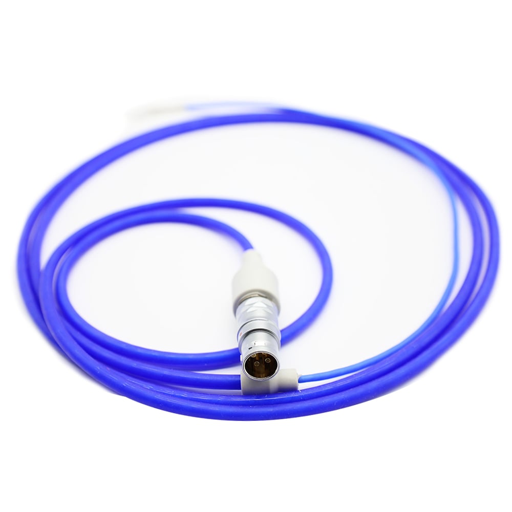
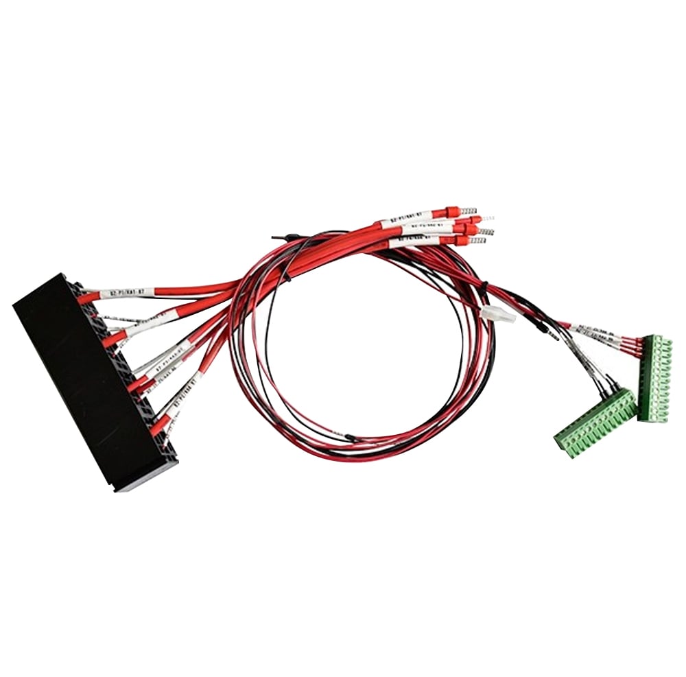
In some sectors such as consumer electronics, robotics and medical technology, off-the-shelf coaxial cables are often a compromise—a general-purpose solution that requires engineers to adapt their designs around existing limitations. The result is inefficiencies—too much cable takes up valuable internal space, a generic interface between the connectors is sub-optimal, and materials that are not specified for a given application tend to wear out in the presence of environmental stressors. At Hotten Electronic Wire Technology, we believe in a different approach: designing RF coaxial assemblies tailored to your precise mechanical, electrical, and environmental requirements. Our R&D team develops hundreds of customized cable solutions every year, supported by our advanced manufacturing capabilities and flexible production capacity, enabling us to deliver assemblies that integrate seamlessly into your product architecture and minimize validation burden. Let's take a look at four engineering and validation benefits that custom designs offer to device makers.
Custom RF coaxial cable assemblies help device manufacturers match the cable to the electrical, mechanical, environmental, and validation requirements of the final system instead of adapting the product around a standard cable.
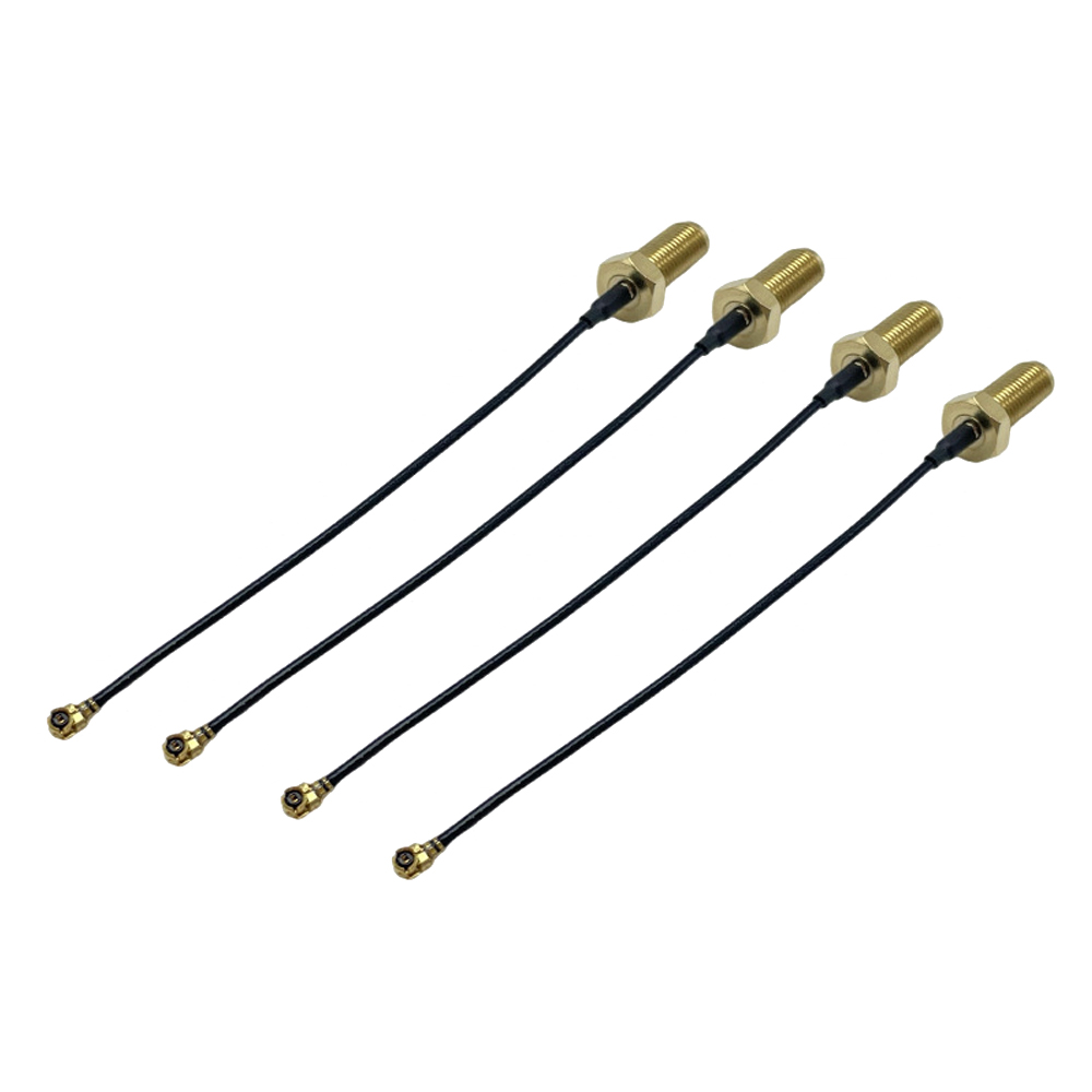
For OEM engineers, the main benefits are better control of characteristic impedance, insertion loss, shielding, cable dimensions, connector termination, routing, flex requirements, and assembly consistency. A custom RF assembly can also simplify prototype validation because the cable is designed as part of the overall signal path rather than treated as a generic accessory.
For high-frequency medical equipment, RF systems, imaging devices, UAV electronics, and compact electronic products, the cable assembly should be selected according to the complete signal path, including the PCB interface, connector, operating frequency, routing space, bending conditions, and required validation tests.
| Engineering requirement | Custom RF cable approach | Why it matters |
|---|---|---|
| Characteristic impedance | Match cable construction to system impedance | Reduces reflections and signal discontinuity |
| Operating frequency | Select suitable conductor, dielectric, shielding, and geometry | Helps control attenuation and high-frequency performance |
| Connector interface | Match connector type, pitch, orientation, and launch geometry | Reduces mechanical and electrical mismatch |
| Cable length | Define exact finished length and routing path | Reduces excess cable and simplifies assembly |
| Shielding | Specify shielding structure and termination | Helps control EMI and unwanted coupling |
| Flexibility | Select suitable jacket, braid, conductor, and strain relief | Supports repeated movement and installation |
| Environmental conditions | Define temperature, moisture, chemicals, sterilization, or vibration requirements | Improves long-term reliability |
| Validation | Establish electrical and mechanical test requirements before production | Reduces late-stage redesign and qualification risk |
A custom RF solution is therefore not simply a cable with a different connector. It is an engineered interconnect designed around the requirements of the device.
For systems requiring controlled RF performance, see HOTTEN's RF Coaxial Cable Assembly and High Frequency & RF Systems solutions.
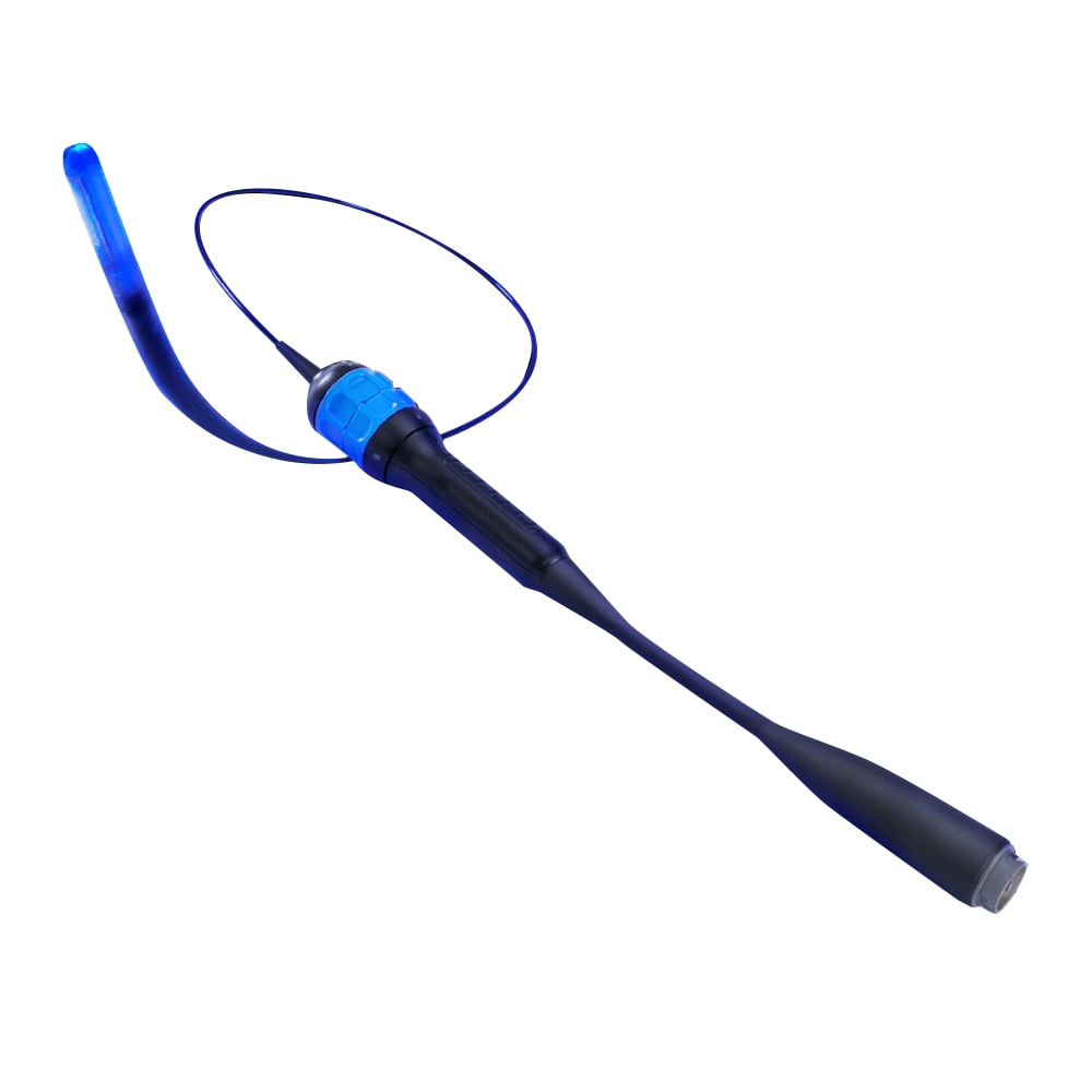
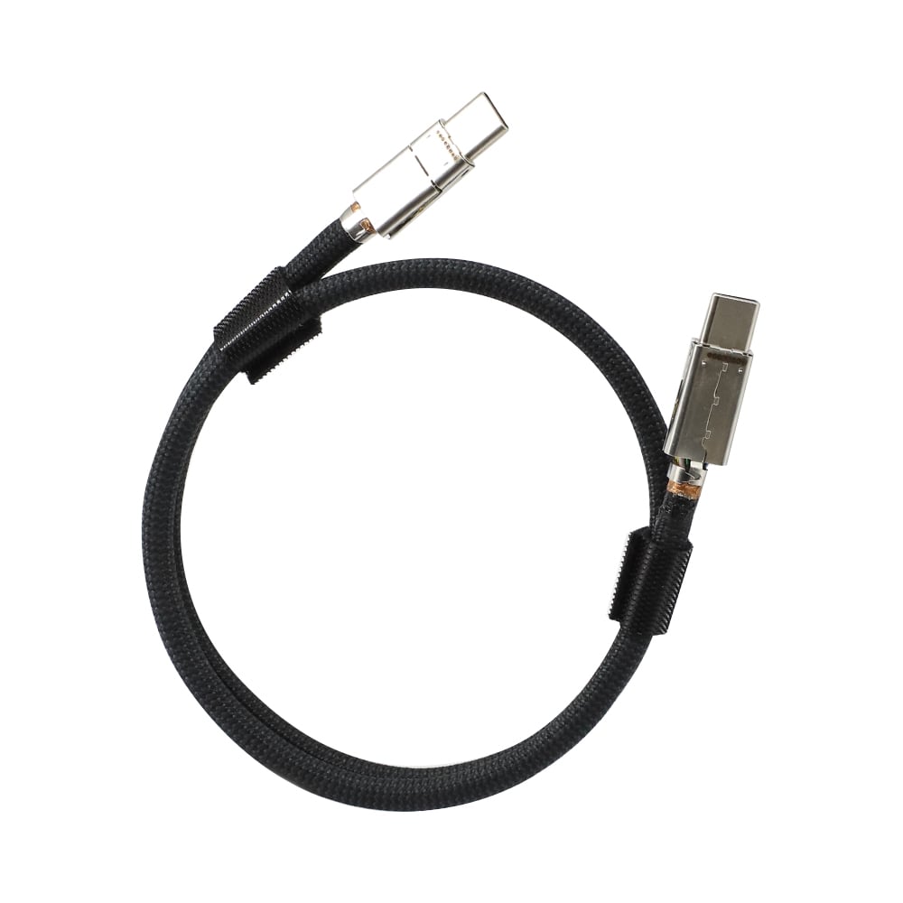
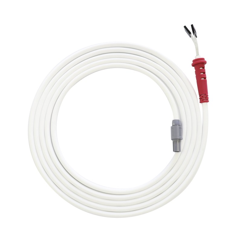
Every electrical system has unique performance requirements, and generic cables will not address the specific electrical characteristics of your system—PCB trace impedances, connector launch geometries, operating frequency bands, and adjacent signal interference. With a custom design approach, Hotten can optimize every electrical parameter to meet your specific requirements. For our AR/VR Cables and USB4 Wire Harnesses, we custom engineer characteristic impedance according to application requirements, including common impedance standards such as 50 Ω and 100 Ω differential impedance, and differential skew to meet the specifications set by the chipset to support reliable high-speed data transmission up to 40 Gbps. For medical applications such as IVUS cables and ICE catheter cables, we optimize attenuation performance for specific medical frequency ranges according to application requirements. While maintaining excellent phase stability. Our engineering team is able to model the performance before the prototype is built using 3D electromagnetic simulation tools to reduce design uncertainty and the need for iterative tuning cycles that slow down product launches. The result is a cable designed to deliver optimal signal integrity from the outset, and without the performance degradation commonly associated with one-size-fits-all solutions.
A cable that is not physically optimized for your product can make installation more complex, be more expensive to work with and create reliability concerns through poorly bent or pinched wires. Hotten's custom assemblies overcome these challenges by creating high dimensional precision and careful mechanical design. We provide these capabilities with precise length control of ±2 mm to avoid wasted space caused by redundant service loops and custom strain relief profiles—overmolded boots, right angle or low profile exits that match your housing geometry. Drone Wire Harnesses and Robotics Wire Harnesses use flexible transition zones for articulating joints and our Endoscope Cables have ultra-slim profiles (down to 0.35mm OD) that can move through narrow instrument channels. Our drawings and 3D models can help your mechanical engineers optimize the PCB layout and routing process, reducing assembly time and minimizing the risk of damage during production.
There are increasing regulatory pressures on device manufacturers—FCC Part 15 for EMI, IEC 60601 for medical electrical safety and UL/CSA for flammability. Often, when testing a generic cable within your final product, the cable integration within your system can introduce unexpected emissions or immunity failures that will require large retesting efforts. Custom assemblies from Hotten make this easy by incorporating component level validation. Pre-testing for RF Cables and LVDS Wire Harnesses is done for shielding effectiveness (up to 100 dB at 1 GHz), and S-parameter datasets are readily provided for use in system-level EMC models. Our ISO 13485 compliant documentation includes process validation reports, material certificates and sterilization validation data, among others, which can be directly used for your 510(k) or CE Mark submissions for medical cables. With this "pre-validated component" approach, you'll lower your testing load, minimize time to market and avoid compliance issues after launch.
Customization does not need to be complex or expose supply chains. The entire customization process from sourcing materials to final assembly is handled in our 10,000㎡ vertically integrated facility by Hotten. Custom tooling components are strategically stored and we provide lifecycle management services such as end-of-life notifications, alternative material qualifications. We have dedicated production lines for high volume OEM programs such as Ultrasound Probe Cables and USB4 Wire Harnesses, where the production process is Cpk controlled and lot-to-lot consistent. We have a quality team that can trace the product back from raw material batch to assembly, enabling rapid root cause identification and corrective action if issues occur. Bringing all custom design, manufacturing, testing to one place means we cut down on the delays, the lag, and the miscommunication and allow device makers to have a partner who will grow with their program. But with Hotten, customization is a strategic approach that enables improved product performance, faster validation, and long-term operational efficiency.
 Hot News
2026-09-17
2026-09-04
2025-12-17
2025-12-11
2025-12-05