
+86-13912615597 [email protected]
All Categories
emi shielding test points for medical cable assemblies in sensitive equipment-0

Technical Articles

Home >  News >  Technical Articles

EMI Shielding Test Points for Medical Cable Assemblies in Sensitive Equipment

Jul 24, 2026

One of the most challenging issues affecting medical equipment reliability is intermittent faults. Signal dropouts, transient noise bursts, and occasional impedance spikes may remain undetected during routine testing but suddenly occur during critical procedures, affecting image quality, ablation therapy, or diagnostic accuracy. These hidden defects often originate at the connector interface, where the cable assembly interfaces with the medical device. The connector is the most used and stressed component in a medical cable assembly, undergoing repeated mating cycles, mechanical stresses, and exposure to environmental contaminants. Connector design is a major consideration at Hotten Electronic Wire Technology, where we have incorporated it into our medical cable design. By incorporating precision contact geometry, proven termination methods and thorough validation procedures, we design our Ultrasound Probe Cables, Endoscope Cables, RF Ablation Cables, EEG Lead Wires, and other medical assemblies to maintain reliable signal integrity. This article discusses four ways connector design helps prevent intermittent faults in clinical environments.

What EMI Shielding Test Points Should Be Evaluated in Medical Cable Assemblies?

Direct Answer

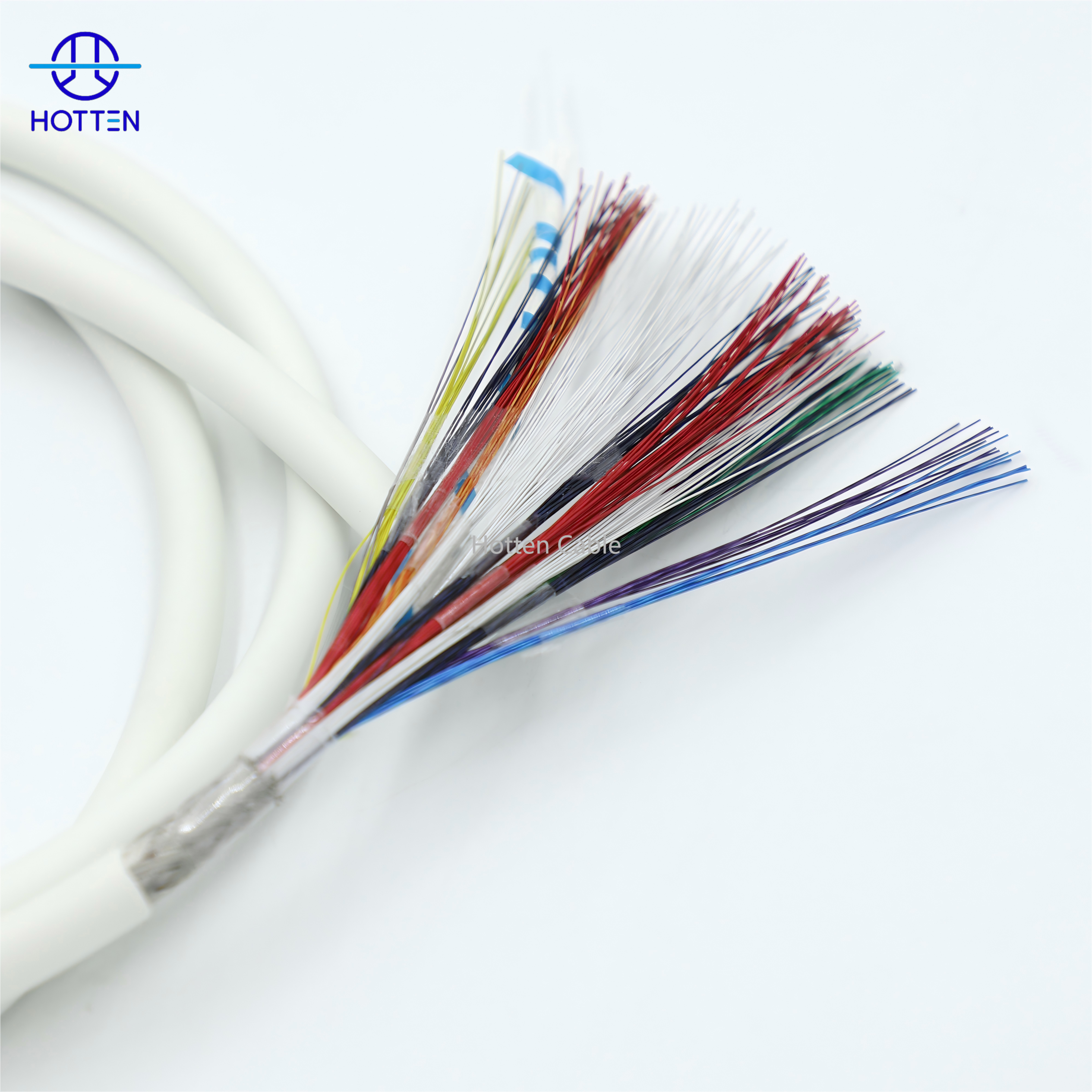
EMI shielding in a medical cable assembly should be evaluated across the entire signal path, not only by checking whether the cable contains a shielding layer.

The main test points include shield coverage, shielding continuity, termination quality, connector transitions, grounding, cable routing, and system-level electromagnetic performance.

For sensitive medical equipment, a cable may still allow unwanted interference if the shield is poorly terminated, interrupted at the connector, or routed too close to noise sources.

EMI shielding test point What to evaluate Why it matters
Shield coverage Foil, braid, individual or overall shielding Determines the basic shielding structure
Shield continuity Electrical continuity along the cable Prevents gaps in the shielding path
Shield termination Connection between shield and connector / ground Critical at cable ends
Connector transition Shield continuity through the connector area Prevents shielding discontinuities
Grounding Ground reference and termination strategy Influences system-level EMI behavior
Cable routing Distance from motors, power supplies and RF sources Reduces unwanted coupling
Shield-to-signal relationship Isolation between signal conductors and shield Helps control coupling
Mechanical protection Stability during flexing and movement Prevents shielding degradation
System-level EMC Performance after installation in the device Confirms the actual integrated result

If the cable carries low-level analog, ultrasound, RF, or other sensitive signals, then shielding should be validated at both the cable and system levels, because a cable's nominal shielding construction does not by itself guarantee the performance of the complete medical device.

For customized applications, HOTTEN provides Medical Cable Assembly and RF Coaxial Cable Assembly solutions.

Precision Contact Geometry for Consistent Electrical Continuity

Common intermittent faults are caused by minute movement of mating connector contacts. Mechanical vibration, thermal expansion, or accidental cable pulling can create temporary contact gaps or the formation of high-resistance oxide films. Hotten's solution comes in the form of precision-machined contacts with optimized normal forces and mating geometries. Our connectors for ICE and IVUS cables maintain low, stable contact resistance even after 500+ mating cycles—featuring gold-over-nickel plating with controlled porosity. We design high retention contacts such as multi-finger sockets and tuned cantilever beams that provide consistent contact force across a wide range of temperatures and throughout the product lifecycle. We validate the stability of contact resistance under simulated clinical vibration (IEC 60601-1), reducing the risk of micro-disconnection issues commonly associated with lower-quality connector designs, so that all connector mating events provide a dependable electrical pathway.

Robust Cable-to-Connector Termination to Eliminate Internal Breakage

Many intermittent faults are actually due to a solder or crimp joint failure between the coaxial cable and the connector pin. Any failure such as a hairline crack, a cold solder joint or insufficient contact compression at the connector interface can create intermittent open circuits or high-resistance paths that fail only under thermal or mechanical stress. Hotten uses automated and process-controlled termination procedures that are medical-grade reliability. Our RF Ablation Cables and Surgical Scalpel Cables are precision resistance welded and ultrasonic bonded to create a durable metallurgical connection designed to withstand the expected service life of the cable assembly. At Hotten, we use controlled-depth stripping and solder-reflow processes for high-strand-count conductors with controlled solder wicking and complete circumferential wetting. Each termination is tested by 3D X-ray and cross section analysis to confirm correct solder fill and crimp geometry and statistical information is generated to monitor the process and ensure that no marginal joints are missed in the factory.

Strain Isolation at the Connector Transition Zone

The highest mechanical stress concentration typically occurs at the transition zone between rigid and flexible sections. Friction between the conductor and shielding components, directly behind the connector, can cause gradual strand breakage which will result in a fault with intermittent high resistance. Hotten creates application-specific, strain isolation systems that shift the flex point from the termination zone. For endoscope and dental sensing cables, we use overmolded flexible grommets with built-in mandrels that distribute bending stress over 20-30mm. Our EEG Lead Wires incorporate spring reinforcement around the boot to absorb tensile loads and prevent stress transfer to the solder joint. We test these designs with 10,000+ flex cycles at high angles, and check for continuity, so clinical handling, whether accidental or routine, doesn't lead to intermittent problems with connections.

Engineering Selection and OEM Validation Considerations

1. Evaluate Shielding as a Complete Signal-Path System

A shield does not work independently of the rest of the cable assembly.

The actual path is:

signal conductor → dielectric → shield → shield termination → connector → PCB ground / chassis → system enclosure

A discontinuity at any of these points can reduce the effectiveness of the overall shielding architecture.

If the medical cable passes between sensitive electronics and a noisy subsystem, then evaluate the shielding structure from connector to connector, because the weakest transition can become the effective EMI entry or exit point.


2. Check Shield Coverage and Construction

Different applications may require different shielding structures.

Common approaches include:

Shield structure Typical engineering consideration
Foil shield High coverage, compact construction
Braided shield Mechanical flexibility and shielding
Foil + braid Combined coverage and mechanical performance
Individual shielding Channel-level isolation
Overall shielding Protection around a cable bundle
Individual + overall shielding Higher isolation for demanding applications

If multiple sensitive channels share a high-density cable, then individual or selectively grouped shielding may need to be considered, because overall shielding alone does not necessarily prevent coupling between adjacent signal paths.

The required structure should therefore be determined from the signal characteristics and system EMI environment.


3. Shield Termination Is One of the Most Important Test Points

A cable can have excellent shield coverage along its length but still perform poorly if the shield is not properly connected at the ends.

The termination area should be checked for:

  • Shield-to-connector contact
  • Ground continuity
  • Termination consistency
  • Exposed shield length
  • Mechanical strain
  • Connector transition
  • Crimp / solder quality

If the shield termination is long, inconsistent, or mechanically unstable, then system-level shielding performance may be affected, because the cable end can become an unintended discontinuity in the shielding path.

For OEM assemblies, shield termination requirements should therefore be included in the engineering drawing rather than left as an undefined manufacturing detail.


4. Connector Transitions Need Their Own EMI Evaluation

The cable body is often not the biggest concern.

The transition between:

cable shield → termination → connector → PCB

can introduce a discontinuity in the electromagnetic structure.

This is especially important when miniature connectors are used in compact medical equipment.

If a shielded cable connects to a high-density connector, then evaluate the connector-side shielding transition separately, because the physical cable may be well shielded while the interface still provides a path for unwanted coupling.

Useful inspection points include:

Connector-area test point What to inspect
Shield termination Is the shield securely connected?
Ground continuity Is the intended ground path maintained?
Contact alignment Is the termination consistent?
Exposed shield Is the exposed length controlled?
Strain relief Does movement stress the shield termination?
Connector shell / ground Is the interface integrated as designed?

5. Shielding Must Be Balanced With Flexibility

Adding shielding layers can improve EMI protection, but it may also change the mechanical behavior of the cable.

Potential trade-offs include:

more shielding → larger OD → higher stiffness → tighter routing constraints

For medical cables that are repeatedly moved, this trade-off becomes particularly important.

If the cable is used in a moving ultrasound probe, endoscope, or other flexible medical assembly, then shielding design should be developed together with bend and flex requirements, because a mechanically unsuitable shield can deteriorate during repeated movement.

HOTTEN's Ultrasound Probe Cable Assembly solutions can combine high-density routing, shielding, fine-wire construction, and application-specific flexibility requirements.


6. Perform Shield Continuity Checks on Finished Assemblies

Shield continuity should be verified on the finished assembly rather than assumed from the raw cable construction.

A practical production check can include:

Shield continuity → connector-side termination → visual inspection → dimensional inspection

The exact test method depends on the cable architecture and the intended electrical interface.

If the finished cable contains multiple termination points or branches, then each relevant shielding path should be verified, because a single incomplete termination can create a discontinuity that is not visible from the outside.


7. Distinguish Cable-Level Shielding From System-Level EMC

Cable shielding is only one component of electromagnetic compatibility.

A medical device can still experience interference because of:

  • PCB layout
  • Power supply noise
  • Motor or actuator emissions
  • Connector geometry
  • Grounding strategy
  • Cable routing
  • Enclosure design
  • Adjacent cables
  • External RF sources

Therefore:

Cable shielding ≠ complete EMC solution

If a system continues to experience EMI after the cable shield has been verified, then investigate routing, grounding, connector interfaces, and other system-level sources, because the cable may not be the only coupling path.


8. Test the Cable Under Representative Mechanical Conditions

For flexible medical devices, shielding performance should not necessarily be evaluated only before mechanical cycling.

Repeated movement can affect:

  • Braid structure
  • Foil integrity
  • Shield termination
  • Connector transition
  • Cable geometry

If the cable is repeatedly bent or twisted during normal use, then inspect electrical and shielding performance after representative mechanical cycling, because initial shielding performance does not demonstrate long-term performance under actual motion.

Relevant validation may include:

Test Purpose
Flex cycling Evaluate cable behavior under repeated bending
Torsion testing Evaluate rotational stress
Pull testing Verify termination strength
Shield continuity Check for electrical discontinuity
Visual inspection Identify mechanical shield damage
Electrical performance test Confirm signal-path stability

9. Define EMI Requirements in the OEM RFQ

“Shielded cable” is too broad to serve as a complete procurement specification.

A more useful RFQ should define:

RFQ parameter Example information
Application Ultrasound, imaging, RF, monitoring, etc.
Signal type Analog, digital, RF, high-speed
Frequency Operating frequency range
Shield type Foil, braid, combined, individual
Coverage Required shielding construction
Termination Shield termination method
Grounding Required connection strategy
Cable OD Maximum allowable diameter
Flex Static / dynamic bending
Environment Temperature, cleaning, vibration, etc.
Validation Shielding / EMC / electrical test requirements
Connector Exact connector or mating interface

If the system has a known EMI problem or defined EMC requirement, then provide the relevant test condition and failure mode during the RFQ stage, because the cable manufacturer can then evaluate the shielding structure against the actual engineering problem.


10. Evaluate Shielding Performance Together With Signal Integrity

For sensitive medical assemblies, shielding and signal transmission should not be treated as separate engineering topics.

The complete evaluation may include:

shielding → capacitance → impedance → attenuation → crosstalk → connector transition → mechanical stability

If the cable carries sensitive ultrasound or high-frequency signals, then evaluate shielding together with capacitance and signal integrity, because changing the shield structure can affect cable diameter, flexibility, electrical geometry, and termination.

This is particularly important for high-density micro coaxial constructions.


11. Build a Practical EMI Validation Plan

A useful OEM validation sequence can be structured as:

Cable construction review → shield continuity → connector termination inspection → electrical testing → mechanical cycling → post-cycle inspection → system-level EMC evaluation

This allows the engineering team to distinguish among:

  • Cable construction problems
  • Shield termination problems
  • Connector-interface problems
  • Mechanical degradation
  • System-level EMI sources

If an EMI issue appears during device validation, then testing each stage separately can help identify whether the root cause lies in the cable, connector transition, grounding, or system integration, because system-level failure alone does not identify the source.

For medical OEM projects requiring controlled shielding and signal transmission, HOTTEN's Medical Cable Assembly, Micro Coaxial Cable, and RF Coaxial Cable Assembly solutions can be developed according to the required electrical, mechanical, and EMI conditions.

Environmental Sealing Against Fluid and Particle Ingress

Any connector interfaces exposed to blood, saline, cleaning solutions, or airborne particulates are susceptible to contamination. Fluid ingress can lead to short circuit between pins and particles can lead to intermittent bridging or abrasive wear of contact surfaces. Hotten uses a number of sealing methods depending on the level of risk associated with the applications. Medical-grade silicone O-rings, potting compounds and labyrinth seals designed to achieve IP68-rated sealing are used in RF Ablation Cables and IVUS Cables. Our Ultrasound Probe Cables have hydrophobic vented connectors to equalize pressure and prevent fluid from entering the connector. All the sealing materials used are biocompatible and tested against common hospital sterilants. Keyed connector housings help prevent incorrect mating and reduce the risk of pin damage, ensure that environmental factors do not contribute to intermittent faults that could compromise patient safety and clinical reliability. Using Hotten's expertise in connector design, medical device OEMs can develop equipment that delivers consistent performance across every procedure.

If you have any suggestions, please contact us

CONTACT US

Get a Free Quote

Our representative will contact you soon.
Email
Phone number
Company Name
Message
0/1000
emi shielding test points for medical cable assemblies in sensitive equipment-1 emi shielding test points for medical cable assemblies in sensitive equipment-2 emi shielding test points for medical cable assemblies in sensitive equipment-3 emi shielding test points for medical cable assemblies in sensitive equipment-4 emi shielding test points for medical cable assemblies in sensitive equipment-5