 EN
EN
Quick Links

One of the most challenging issues affecting medical equipment reliability is intermittent faults. Signal dropouts, transient noise bursts, and occasional impedance spikes may remain undetected during routine testing but suddenly occur during critical procedures, affecting image quality, ablation therapy, or diagnostic accuracy. These hidden defects often originate at the connector interface, where the cable assembly interfaces with the medical device. The connector is the most used and stressed component in a medical cable assembly, undergoing repeated mating cycles, mechanical stresses, and exposure to environmental contaminants. Connector design is a major consideration at Hotten Electronic Wire Technology, where we have incorporated it into our medical cable design. By incorporating precision contact geometry, proven termination methods and thorough validation procedures, we design our Ultrasound Probe Cables, Endoscope Cables, RF Ablation Cables, EEG Lead Wires, and other medical assemblies to maintain reliable signal integrity. This article discusses four ways connector design helps prevent intermittent faults in clinical environments.
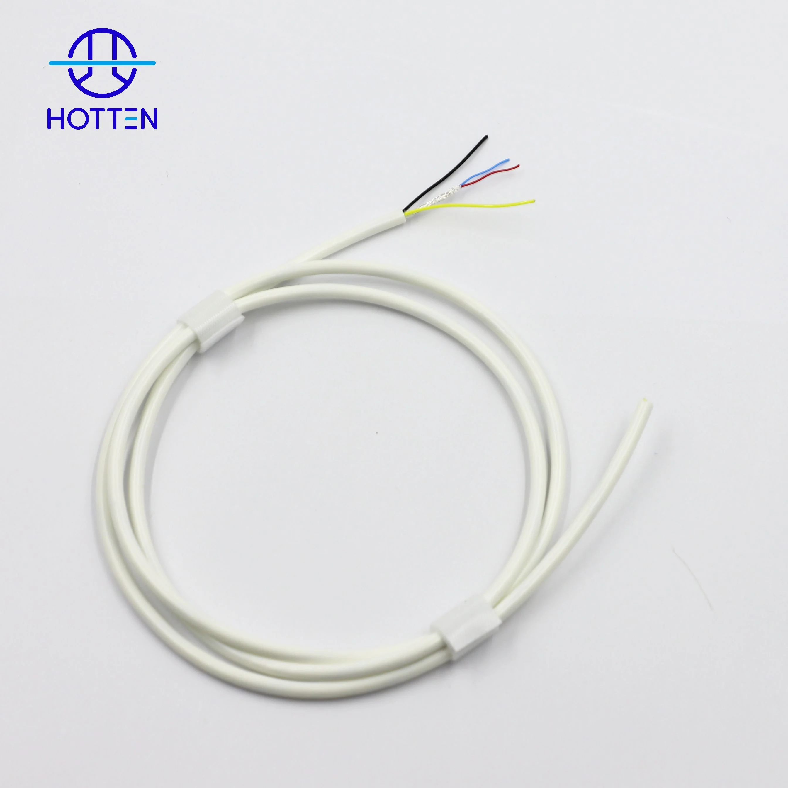
Connector design plays a critical role in preventing intermittent faults in medical equipment because the connector is the transition point between the cable and the device's electrical system.
An intermittent fault can occur even when the cable itself is electrically continuous. Causes may include poor contact force, connector misalignment, inadequate termination, mechanical stress, insufficient strain relief, vibration, repeated mating, or damage around the cable-to-connector transition.
For medical cable assemblies, reliable connector design therefore requires coordination between:
connector → contacts → cable termination → strain relief → shielding → mechanical routing → inspection and testing
| Connector factor | What should be controlled | Why it matters |
|---|---|---|
| Contact interface | Contact geometry and mating condition | Maintains electrical connection |
| Connector pitch | Correct alignment and assembly | Important for miniature interfaces |
| Termination | Crimp, solder or other approved method | Prevents unstable electrical joints |
| Strain relief | Controls cable movement at connector | Reduces mechanical stress |
| Connector retention | Locking / retention structure | Prevents unintended separation |
| Cable exit | Bend direction and transition geometry | Avoids localized stress |
| Shield termination | Consistent shield connection | Helps maintain EMI performance |
| Mating cycles | Connector durability under intended use | Important for repeatedly connected equipment |
| Inspection | Dimensional, visual and electrical checks | Detects assembly variation |
| Validation | Mechanical and electrical testing | Confirms performance under use conditions |
If a medical cable is frequently moved, connected, disconnected, or exposed to vibration, then connector design should be treated as part of the complete cable reliability system, because intermittent faults often originate at interfaces rather than in the middle of the cable.
For customized applications, HOTTEN provides Medical Cable Assembly solutions with application-specific connector and termination requirements.
Common intermittent faults are caused by minute movement of mating connector contacts. Mechanical vibration, thermal expansion, or accidental cable pulling can create temporary contact gaps or the formation of high-resistance oxide films. Hotten's solution comes in the form of precision-machined contacts with optimized normal forces and mating geometries. Our connectors for ICE and IVUS cables maintain low, stable contact resistance even after 500+ mating cycles—featuring gold-over-nickel plating with controlled porosity. We design high retention contacts such as multi-finger sockets and tuned cantilever beams that provide consistent contact force across a wide range of temperatures and throughout the product lifecycle. We validate the stability of contact resistance under simulated clinical vibration (IEC 60601-1), reducing the risk of micro-disconnection issues commonly associated with lower-quality connector designs, so that all connector mating events provide a dependable electrical pathway.
Many intermittent faults are actually due to a solder or crimp joint failure between the coaxial cable and the connector pin. Any failure such as a hairline crack, a cold solder joint or insufficient contact compression at the connector interface can create intermittent open circuits or high-resistance paths that fail only under thermal or mechanical stress. Hotten uses automated and process-controlled termination procedures that are medical-grade reliability. Our RF Ablation Cables and Surgical Scalpel Cables are precision resistance welded and ultrasonic bonded to create a durable metallurgical connection designed to withstand the expected service life of the cable assembly. At Hotten, we use controlled-depth stripping and solder-reflow processes for high-strand-count conductors with controlled solder wicking and complete circumferential wetting. Each termination is tested by 3D X-ray and cross section analysis to confirm correct solder fill and crimp geometry and statistical information is generated to monitor the process and ensure that no marginal joints are missed in the factory.
A complete open circuit is usually easier to detect.
An intermittent fault can occur only under specific conditions, such as:
The equipment may therefore operate normally during a static inspection but fail when the cable is moved.
If a device passes a continuity test but experiences occasional signal loss during operation, then the connector and cable transition should be investigated together, because static continuity does not necessarily reproduce the mechanical conditions that trigger an intermittent connection.
The contact interface must maintain a stable electrical connection throughout the intended operating conditions.
Relevant considerations include:
If contact force or mating alignment is insufficient, then small amounts of vibration or movement can cause resistance variation or momentary signal interruption, because the electrical interface is no longer mechanically stable.
For sensitive medical signals, even a brief interruption may affect system operation or create diagnostic or monitoring issues, depending on the device architecture.
Medical equipment increasingly uses compact connectors and high-density cable assemblies.
As connector size and pitch decrease, assembly becomes more sensitive to:
If a miniature connector is used with fine-wire or micro coaxial cable, then assembly alignment should be tightly controlled, because small positional errors can affect contact engagement or place excessive force on the termination.
This is particularly relevant for:
A connector can be mechanically correct while the actual cable termination is unstable.
Common termination methods include:
Each process requires appropriate control.
| Termination issue | Potential result |
|---|---|
| Insufficient crimp | High or unstable contact resistance |
| Excessive crimp | Conductor or contact damage |
| Poor solder joint | Intermittent electrical connection |
| Incorrect stripping | Conductor / insulation damage |
| Misalignment | Poor connector mating |
| Inadequate strain relief | Stress transferred to termination |
| Shield termination defect | EMI or grounding problem |
If cable movement is transferred directly into the termination area, then even a correctly assembled connector can experience long-term degradation, because repeated mechanical stress is concentrated at the cable exit and contact interface.
A properly designed strain relief creates a controlled transition between the flexible cable and rigid connector.
Its purpose is to reduce concentrated mechanical stress at:
cable jacket → termination → contact → connector housing
Common approaches include:
If the cable is repeatedly bent immediately next to the connector, then appropriate strain relief becomes particularly important, because uncontrolled bending can gradually damage conductors, shielding, insulation, or termination points.
The correct strain-relief geometry depends on the cable construction and actual bending conditions.
Connector orientation is sometimes treated as a packaging detail, but it can affect reliability.
Examples include:
A poorly chosen exit direction can force the cable into an excessively tight bend immediately after installation.
If the available routing space naturally requires the cable to turn immediately after the connector, then connector orientation and strain relief should be designed around the routing path, because forcing a straight connector into an unsuitable path can increase local mechanical stress.
For OEM projects, connector orientation should therefore be included in the mechanical drawing rather than decided only during final assembly.
Some medical equipment uses detachable cables that are connected and disconnected repeatedly.
In these applications, connector selection should consider the intended mating conditions.
Relevant factors include:
If the cable is frequently replaced or disconnected by operators, then connector durability and mating guidance should be part of supplier qualification, because a connector that works well during initial assembly may behave differently after repeated mating.
In shielded medical cable assemblies, the connector transition must maintain the intended shielding path.
The engineering chain is:
cable shield → shield termination → connector → ground / chassis interface
A weak or inconsistent connection can create two problems simultaneously:
mechanical instability + electromagnetic discontinuity
If a cable carries sensitive ultrasound, analog, RF, or high-speed signals, then shield termination should be inspected and tested as part of the finished connector assembly, because connector reliability is not only about signal contact; the shielding path can also be affected.
For RF-oriented applications, HOTTEN provides RF Coaxial Cable Assembly solutions.
A simple continuity test is useful but may not reproduce an intermittent failure.
For example:
static continuity test → PASS
but:
bend / vibration / pull + electrical monitoring → FAIL
A more representative validation approach may combine mechanical movement with electrical monitoring.
| Test condition | What it can reveal |
|---|---|
| Static continuity | Basic open / short conditions |
| Flex while monitored | Intermittent contact under bending |
| Pull test | Termination weakness |
| Torsion | Cable-to-connector stress |
| Vibration | Contact stability |
| Repeated mating | Contact wear or retention issues |
| Temperature cycling | Mechanical / material changes |
| Post-test continuity | Permanent degradation |
If intermittent failures occur only during movement, then the validation method should include movement while monitoring electrical continuity or signal performance, because a static test may not reproduce the actual failure condition.
Not every connector is suitable for every medical cable.
The electrical requirements differ between:
Important considerations can include:
| Signal type | Connector considerations |
|---|---|
| Sensitive analog | Contact stability and shielding |
| Ultrasound | Channel density, capacitance and reliability |
| High-speed digital | Signal integrity and controlled interfaces |
| RF | Impedance and connector transition |
| Power | Current capacity and contact reliability |
If the cable carries high-frequency or sensitive signals, then connector geometry and electrical interface characteristics should be evaluated together with the cable, because the connector can become part of the signal path and introduce discontinuities.
For OEM production, connector reliability depends on more than the connector component itself.
The manufacturing process should control:
connector incoming inspection → cable preparation → termination → alignment → strain relief → shielding → electrical test → mechanical inspection
Useful supplier-qualification questions include:
If the connector is a critical component in a medical cable assembly, then its incoming material, assembly process, and finished-product inspection should all be controlled, because a high-quality connector component can still become an unreliable assembly if the termination process is inconsistent.
A cable assembly RFQ should provide the manufacturer with enough information to understand the interface.
Recommended information includes:
| RFQ item | Information to provide |
|---|---|
| Connector manufacturer | Brand / supplier |
| Connector series | Exact series |
| Part number | Exact PN where possible |
| Mating interface | Mating connector information |
| Contact count | Number of contacts |
| Pitch | Contact spacing |
| Orientation | Straight / right-angle / custom |
| Termination | Crimp / solder / other |
| Cable | Conductor, coax or cable construction |
| Shielding | Shield termination requirement |
| Strain relief | Geometry / material requirement |
| Mating cycles | Expected usage |
| Environment | Temperature, cleaning, vibration, etc. |
| Testing | Electrical and mechanical validation |
| Drawing | 2D / 3D mechanical information |
If the connector has not yet been finalized, then provide the mechanical envelope, mating interface, signal requirements, and cable routing constraints, because the supplier can evaluate connector compatibility before the design is locked.
For a new medical cable assembly, OEM teams can structure validation as:
Connector selection → termination process development → prototype assembly → static electrical testing → mechanical testing → monitored continuity / signal testing → environmental testing where required → final inspection → production approval
The objective is to validate not just the connector component, but the complete interface.
If the cable assembly will be subjected to repeated bending or handling, then post-mechanical-cycle electrical testing should be included, because connector and termination degradation may not be visible during initial inspection.
A medical cable manufacturer should understand that connector reliability is connected to the entire cable construction.
The supplier should be capable of coordinating:
cable diameter → conductor construction → shielding → connector → termination → strain relief → testing
This is particularly important for miniature and high-density assemblies.
If the project uses ultra-fine wire, micro coaxial cable, or fine-pitch connectors, then supplier qualification should include actual termination capability and inspection methods, because these assemblies are more sensitive to manufacturing variation than conventional cable assemblies.
For advanced medical applications, HOTTEN provides Medical Cable Assembly, Micro Coaxial Cable Assembly, and Ultrasound Probe Cable Assembly solutions with customized connector and termination requirements.
The highest mechanical stress concentration typically occurs at the transition zone between rigid and flexible sections. Friction between the conductor and shielding components, directly behind the connector, can cause gradual strand breakage which will result in a fault with intermittent high resistance. Hotten creates application-specific, strain isolation systems that shift the flex point from the termination zone. For endoscope and dental sensing cables, we use overmolded flexible grommets with built-in mandrels that distribute bending stress over 20-30mm. Our EEG Lead Wires incorporate spring reinforcement around the boot to absorb tensile loads and prevent stress transfer to the solder joint. We test these designs with 10,000+ flex cycles at high angles, and check for continuity, so clinical handling, whether accidental or routine, doesn't lead to intermittent problems with connections.
Any connector interfaces exposed to blood, saline, cleaning solutions, or airborne particulates are susceptible to contamination. Fluid ingress can lead to short circuit between pins and particles can lead to intermittent bridging or abrasive wear of contact surfaces. Hotten uses a number of sealing methods depending on the level of risk associated with the applications. Medical-grade silicone O-rings, potting compounds and labyrinth seals designed to achieve IP68-rated sealing are used in RF Ablation Cables and IVUS Cables. Our Ultrasound Probe Cables have hydrophobic vented connectors to equalize pressure and prevent fluid from entering the connector. All the sealing materials used are biocompatible and tested against common hospital sterilants. Keyed connector housings help prevent incorrect mating and reduce the risk of pin damage, ensure that environmental factors do not contribute to intermittent faults that could compromise patient safety and clinical reliability. Using Hotten's expertise in connector design, medical device OEMs can develop equipment that delivers consistent performance across every procedure.
 Hot News
2026-09-17
2026-09-04
2025-12-17
2025-12-11
2025-12-05