 EN
Quick Links

In the advanced medical and consumer electronic applications, from robotic medical arms to small AR/VR headsets, space is at a premium. Developers progressively depend on ultra-fine coaxial cables to transfer fast data as well as energy within these firmly loaded, dynamic assemblies. A crucial, however frequently misinterpreted, spec for these micro workhorses is the minimal bending radius. Surpassing this restriction can easily result in devastating signal failure. However, exactly what specifies this essential specification? It's not a single value, however, the complicated interaction of physics, products, and technical style.
The Core Conundrum: Material Stress and Strain
The essential restriction is governed through product science, specifically, stress and strain . When a cable is curved, its own external surface extends (tension), as well as its own internal surface compresses. For the main conductor, generally made from copper or even silver-plated copper, extreme as well as duplicated stress results in work hardeningas well as ultimate fatigue fracture. The thinner the conductor (such as AWG 44 or even finer), the much a lot extra severe this tension focus ends up being for a given bend radius. For that reason, the very initial definer of the bending radius is the ductility as well as tiredness protection of the conductor alloy, as well as its own stranding style. A carefully stranded conductor can easily withstand tighter flexes compared to a strong one, a concept crucial for the durability of Robotics Wire Harnesses as well as gimbal video cable harnesses, where movement is continuous.
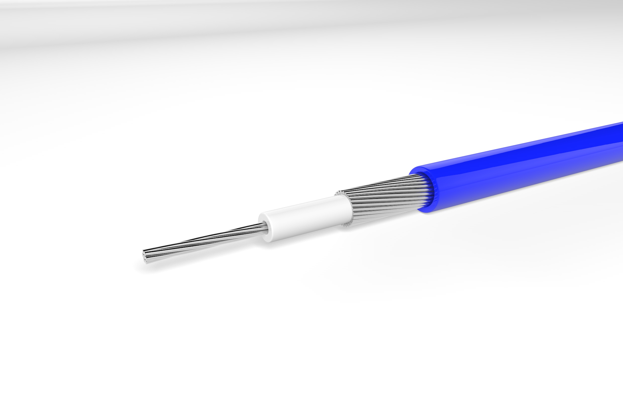
The minimum bend radius of an ultra-fine coaxial cable is determined by the conductor structure, dielectric, shielding, jacket, cable diameter, construction method, and whether the cable is used in static or dynamic bending.
A smaller cable does not automatically mean that it can be bent more tightly. The cable must maintain its electrical and mechanical structure while being routed through the required path.
For OEM applications, the practical bend-radius limit should therefore be evaluated together with:
cable OD + conductor construction + shielding + jacket + bending direction + flex cycle + installation method
| Factor | Effect on bend radius |
|---|---|
| Conductor structure | Influences fatigue and resistance to repeated bending |
| Cable OD | Affects the physical bending geometry |
| Dielectric | Must maintain its position and electrical characteristics |
| Shielding | Can limit flexibility and withstand repeated movement |
| Jacket | Influences overall stiffness and surface durability |
| Termination | Creates a rigid transition near the connector |
| Bend direction | Different motion profiles create different stresses |
| Static vs. dynamic use | Dynamic bending requires different validation |
| Bend cycle count | Repeated movement can cause fatigue |
| Temperature | Can change material flexibility |
| Cable routing | Tight installation can create local stress |
If an ultra-fine coaxial cable must be routed through a small moving mechanism, then the minimum bend radius should be defined from the actual operating condition rather than from cable diameter alone, because repeated bending can affect both cable structure and electrical performance.
For customized applications, see HOTTEN's Micro Coaxial Cable and Micro Coaxial Cable Assembly solutions.
The Dielectric Dilemma: Compression Set and Electrical Stability
Bordering the conductor is the dielectric protection. This product should certainly not just be versatile but also durable. When curved as well dramatically, smooth dielectrics can easily go through long-term contortion (compression set), producing a weaker factor that alters the cable's geometry. This contortion modifies the crucial range between the facility conductor and the guard, disrupting the managed impedance, a can severely affect signal integrity in USB4 cable harnesses or even LVDS cable harnesses for 4K endoscopes. The bending radius should be sufficiently large to guarantee the dielectric springs return to their own initial form, preserving a steady stable electrical performance over repeated bending cycles.
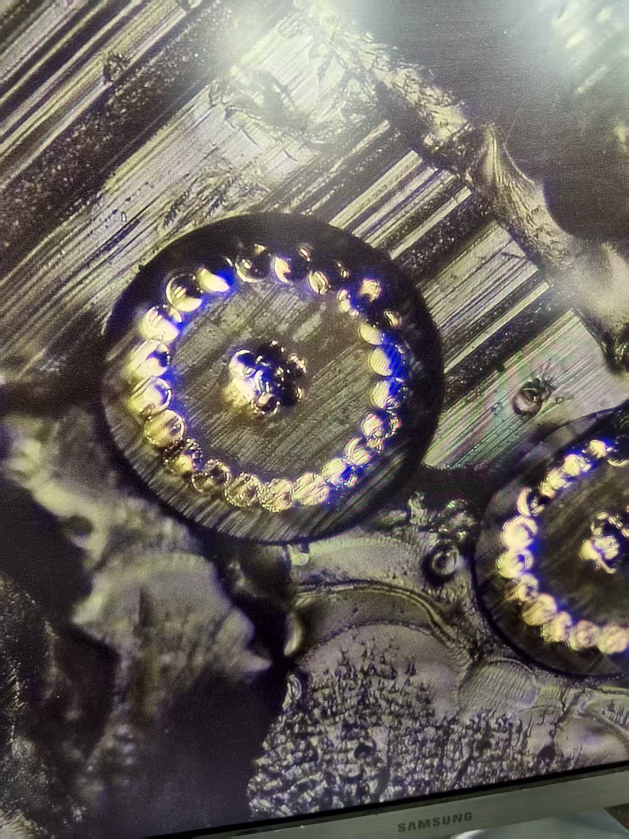
The protective layer is one of the most susceptible to bending damage. A foil guard can easily break as well as different, while a penalty intertwined or even offered guard can easily struggle with damaged hairs as well as enhanced electric protection under limited, duplicated bending. A jeopardized guard significantly enhances signal attenuation as well as electromagnetic interference (EMI) vulnerability, enabling sound to interfere with sensitive signals in EEG top cables or even enabling discharges coming from RF ablation cables to disrupt other devices. The minimal bending radius is specified due to the factor at which the shield's design starts to deteriorate, shedding its own 100% protection as well as background effectiveness. This is an essential factor to consider in the style of our ultrasound probe cables as well as endoscope cables.
Static Bending vs Dynamic Bending
The System Synergy: Jacket, Lay, and Application-Specific Demands
| Bending Condition | Typical Requirement | Key Concern |
|---|---|---|
| Static Bend | Cable remains in one position | Installation stress |
| Occasional Bend | Limited movement | Mechanical fatigue |
| Repeated Dynamic Bend | Continuous movement | Conductor and shield fatigue |
| Continuous Flexing | Robotic or articulating systems | Long-term cycle life |
The first question is how the cable moves.
A cable installed once and left in position has a different requirement from a cable that bends thousands of times during normal operation.
| Application condition | Main requirement |
|---|---|
| Static routing | Cable can tolerate installation bend without damage |
| Occasional movement | Limited repeated bending |
| Continuous movement | Dynamic flex life |
| Bending + twisting | Combined flex and torsion |
| Robotic movement | Repeated controlled motion |
| Probe / endoscope | Frequent bending and handling |
If the cable remains stationary after installation, then the key concern is avoiding excessive installation stress, because the cable does not experience continuous cycling.
If the cable bends repeatedly during operation, then flex-life validation should be performed at a defined bend radius, because static installation performance does not demonstrate dynamic durability.
Engineers sometimes estimate bend radius using cable diameter, but OD alone does not define cable flexibility.
Two cables with similar OD can behave differently because of differences in:
If two micro coaxial cables have similar outer diameters but different internal constructions, then their minimum bend radii can still be different, because flexibility is determined by the complete structure.
For this reason, OEM specifications should define the required cable construction and bend performance, not just OD.
The conductor must withstand mechanical strain as the cable bends.
Relevant design variables include:
If the cable is used in a repeated-bending application, then conductor construction should be selected together with the bend-radius requirement, because the center conductor is subjected to repeated mechanical strain during operation.
This becomes especially important as conductor size decreases and the cable is routed through small moving components.
In a coaxial cable, the dielectric is part of the electrical structure between the center conductor and shield.
During bending, the internal geometry changes.
The design therefore needs to maintain acceptable:
If the dielectric shifts significantly during bending, then the cable's electrical characteristics can change, because coaxial geometry is part of the impedance and capacitance relationship.
For high-frequency applications, this means bend-radius selection should consider electrical performance as well as mechanical survival.
A shield provides electrical protection, but its construction also affects bending behavior.
Possible structures include:
Different structures have different mechanical behavior.
If the application requires repeated bending, then the shielding structure should be evaluated for fatigue and flexibility, because a shield that provides strong EMI protection can still become too stiff for the required motion.
This is particularly relevant for high-density micro coaxial assemblies used in:
The outer jacket protects the cable, but its stiffness and thickness contribute to the finished cable's bending behavior.
Important jacket parameters include:
| Parameter | Engineering consideration |
|---|---|
| Material | Flexibility and environmental durability |
| Thickness | Adds mechanical stiffness and affects OD |
| Hardness | Influences bending resistance |
| Surface friction | Can affect routing and handling |
| Abrasion resistance | Important for repeated movement |
If a flexible application requires both small bend radius and durable surface protection, then jacket material and thickness should be optimized together, because an excessively rigid outer layer can become the limiting factor even when the internal cable is flexible.
The cable is flexible, but the connector and termination are much more rigid.
This creates a transition:
flexible cable → strain relief → termination → connector
The transition area can experience concentrated stress if the cable is forced to bend immediately after the connector.
If a cable must bend close to the connector, then connector orientation and strain relief should be designed together with the bend radius, because the rigid termination area can become the weakest mechanical point.
For OEM cable assemblies, the drawing should therefore specify the cable exit direction and the available bend space around the connector.
Tighter bending increases the mechanical strain experienced by the cable structure.
As the bend becomes tighter, potential risks include:
If the required installation uses a bend radius close to the cable's physical limit, then representative mechanical testing should be performed, because a cable that survives a single static bend may still fail under repeated movement.
A useful flex-life specification should define more than:
“10,000 bending cycles”
The test should also specify:
| Test parameter | What should be defined |
|---|---|
| Bend radius | Test radius |
| Motion | Bending direction / path |
| Speed | Cycling frequency |
| Travel | Movement distance |
| Tension | Cable load |
| Torsion | Whether twisting is included |
| Temperature | Test environment |
| Cycle count | Required number of cycles |
| Failure criterion | Electrical / mechanical acceptance |
If an OEM specifies only a cycle count without the test conditions, then the requirement may be difficult to compare between suppliers, because flex-life results depend strongly on the test setup.
Mechanical survival alone does not prove that the cable remains electrically suitable.
After repeated bending, OEMs may need to check:
If the cable carries sensitive high-frequency or high-speed signals, then post-flex electrical testing should be included where relevant, because mechanical deformation can affect electrical characteristics before a complete open or short circuit occurs.
For high-frequency applications, see HOTTEN's RF Coaxial Cable Assembly.
A cable can bend without significant twisting, but some applications impose both at the same time.
Examples include:
If the cable experiences both bending and rotation, then torsional requirements should be included in validation, because a cable that performs well under pure bending may behave differently when torsion is added.
Cable materials can respond differently at different temperatures.
Changes in temperature may affect:
If the cable operates across a wide temperature range, then bend performance should be evaluated at representative operating temperatures, because a cable that is flexible at room temperature may not behave identically at temperature extremes.
This is particularly relevant for medical, UAV, outdoor, and industrial imaging applications.
A practical OEM specification should distinguish:
installation bend radius
from:
operating bend radius
and, where relevant:
dynamic flex-test radius
For example:
| Requirement | Specification |
|---|---|
| Installation | Maximum temporary bend during assembly |
| Static operation | Minimum permanent routing radius |
| Dynamic operation | Minimum radius during repeated movement |
| Flex testing | Defined test radius and cycle count |
| Connector area | Separate transition-radius requirement |
If the cable operates inside a moving mechanism, then the dynamic bend radius should be treated as a system requirement, because the cable's movement path is part of the final mechanical design.
Different applications create different bend-radius priorities.
| Application | Main bending concern |
|---|---|
| Ultrasound probe | Repeated bending and torsion |
| Endoscope | Tight-radius repeated bending |
| Robotic vision | Dynamic movement inside joints |
| Gimbal camera | Repeated bending and rotation |
| UAV camera | Compact routing and vibration |
| Medical imaging | Compact routing plus signal integrity |
| Fixed RF equipment | Installation bend and connector transition |
If the cable is used in a moving camera or robotic mechanism, then dynamic bend performance should receive more attention than static flexibility, because service life depends on repeated movement.
For UAV and robotics applications, see UAV & Robotics.
Before requesting a quotation for an ultra-fine coaxial cable assembly, provide:
| RFQ item | Recommended information |
|---|---|
| Application | Medical, UAV, robotics, camera, RF, etc. |
| Cable OD | Required maximum |
| Bend radius | Installation / operating / dynamic |
| Flex cycles | Required cycle count |
| Motion | Bend, torsion or combined |
| Speed | Required cycling speed |
| Conductor | AWG and material |
| Cable structure | Micro coaxial construction |
| Shielding | Required structure |
| Jacket | Material / environmental requirements |
| Cable length | Finished length |
| Connector | Manufacturer and part number |
| Strain relief | Required geometry |
| Environment | Temperature, vibration, chemicals |
| Testing | Mechanical and electrical requirements |
| Quantity | Prototype / pilot / mass production |
If the OEM supplies the actual routing path or 3D mechanical envelope, then the supplier can evaluate the cable against the real installation conditions, because bend-radius requirements are strongly dependent on how the cable is installed and moved.
Before approving a micro coaxial cable for production, verify:
| Checkpoint | Key question |
|---|---|
| Cable construction | Is the internal structure suitable for bending? |
| OD | Does the cable fit the routing envelope? |
| Static bend | Can it survive installation and fixed routing? |
| Dynamic bend | Can it withstand repeated movement? |
| Torsion | Is rotational movement included where required? |
| Shielding | Will the shield maintain its function after bending? |
| Termination | Is the connector transition adequately protected? |
| Environment | Has temperature been considered? |
| Electrical | Is performance checked before / after flexing? |
| Production | Can the required construction be reproduced consistently? |
The practical goal is not simply to specify the smallest possible bend radius.
It is to identify the minimum radius at which the complete cable assembly can maintain its mechanical integrity and required electrical performance under the actual conditions of the device.
For OEM applications requiring flexible, ultra-fine interconnects, see HOTTEN's Micro Coaxial Cable, Micro Coaxial Cable Assembly, and Medical Cable Assembly solutions.
A: The minimum bending radius depends on the conductor construction, dielectric material, shielding structure, jacket material and whether the cable is used in a static or dynamic bending application. There is no single bending radius suitable for every ultra-fine coaxial cable.
A: Excessive bending can deform the conductor, dielectric and shielding layers, potentially causing impedance changes, signal loss, EMI susceptibility and premature mechanical failure.
A: Yes. A cable used for continuous movement generally requires a different bending specification and fatigue validation than a cable that is bent once during installation.
A: Yes. Conductor construction, dielectric materials, shielding, jacket materials and overall cable geometry can be customized according to the required bending radius, movement pattern and electrical performance.
A: Applications such as medical imaging equipment, robotic systems, gimbal cameras, endoscopes, AR/VR devices and other compact electronic systems may require highly flexible ultra-fine coaxial cables.
Lastly, the bending radius is specified due to the finished cable setting up. A tough coat product can easily assist disperse tension, however might also limit motion if as well rigid. Much more significantly, in a multi-conductor assembly (typical in ICE cables or even IVUS cables), the interior lay geometry is essential. A regulated, helical lay enables private cables to relocate about one another throughout a bend, producing a neutral axis that reduces private conductor stress. The supreme restriction is determined due to the most demanding problem: Is it a single setup bend or even a vibrant bending pattern over countless movements? The appropriate radius for a fixed oral noticing cable will certainly be much smaller compared to that of a continuously articulating medical robotic harness.
At Hotten Electronic Wire Technology, minimum bending radius is defined through conductor design, dielectric selection, shielding structure, and dynamic fatigue validation testing. With a precise choice of conductor stranding, dielectric polymers, guard design, as well as general assembly style, our team specifies as well as validate bending frontiers that guarantee long-lasting dependability and signal stability. For our customers in medical as well as modern markets, this implies a cable service that suits their type of element without risking the efficiency that specifies their product.
 Hot News
2026-09-17
2026-09-04
2025-12-17
2025-12-11
2025-12-05