 EN
Quick Links

As the medical diagnostics world continuously evolves, high-frequency signal integrity is critical to image clarity and diagnostic accuracy. Intracardiac echocardiography (ICE), which relies on high-frequency ultrasound signals and low-loss signal transmission, is one example of a medical imaging application where cable performance can affect system reliability, is one example of the many technologies that enable the difference between a usable image and diagnostically valuable information. For these high-performance applications, coaxial cable assemblies are the transmission lines of choice. At Hotten, we design these assemblies so that the signal's phase, amplitude and timing are all preserved. Understanding the behavior of coaxial technology at extreme frequencies is a critical factor for the reliability and performance of any medical device engineer's design.
Coaxial cable assemblies are commonly considered for high-frequency medical signal transmission because the cable structure provides a defined signal path with controlled impedance and shielding around the signal conductor.
For medical imaging systems, the cable is part of the complete signal chain. Engineers may need to consider signal frequency, attenuation, impedance, capacitance, shielding, cable length, conductor construction, cable diameter, connector design, and mechanical flexibility together.
If → the medical device carries high-frequency imaging signals
Then → evaluate a controlled coaxial cable structure
Why → signal transmission depends on the geometry and electrical characteristics of the complete transmission path.
If → the system is sensitive to signal loss
Then → evaluate conductor construction, dielectric structure, cable length and connector transitions
Why → insertion loss is affected by more than the conductor material alone.
If → multiple signal channels must fit inside a compact medical device
Then → evaluate multi-core micro coaxial cable assemblies
Why → compact coaxial structures can support high-density signal routing.
If → the cable is routed through a moving medical instrument
Then → evaluate shielding, cable OD, flexibility and termination together
Why → electrical requirements must be maintained within the available mechanical space and movement conditions.
HOTTEN's medical cable assembly solutions currently include customized cable dimensions, conductors, shielding, insulation materials, connectors and assembly configurations.
For compact medical signal connections, see Micro Coaxial Cable Assembly.
For medical application-level solutions, see Medical Equipment.
The Physics of Shielding: Protecting Signal Integrity
High-frequency medical signals are susceptible to external electromagnetic interference (EMI) and internal crosstalk. Compared with twisted-pair and ribbon cable, the main benefit of coaxial assemblies is that they have a concentric structure consisting of a central conductor, dielectric insulator, metallic shield and outer jacket. This concentric geometry contains electromagnetic fields within the cable, preventing signal radiation while also blocking external noise from penetrating. We use double shielding, silver plated copper braid and aluminum-polyester foil, for Hotten's ICE Cables and IVUS Cables, which are used in the frequency range from 20 MHz to 60 MHz and during the rotational pullback. This dual-layer shielding structure helps reduce electromagnetic interference and protect sensitive medical signals from external noise, this level of shielding helps protect received echo signals from interference generated by operating-room equipment, including diathermy and fluoroscopy systems.
Controlled Impedance: Essential for Signal Integrity
Slight geometry variations in cables can cause impedance discontinuities at high frequencies, leading to reflections, standing waves and amplitude ripple, all of which will affect image resolution. Coaxial assemblies are designed to ensure that the characteristic impedance is closely controlled to 50Ω or 75Ω, by careful control of the ratio of inner conductor diameter to the inner shield diameter and the dielectric constant of the insulator material. Hotten's ultrasound probe cables are rigorously tested by time-domain reflectometry (TDR) to ensure impedance deviation remains within ±2 Ω. The RF Cables we make for surgical ablation and imaging have extruded PTFE (polytetrafluoroethylene) dielectrics with a stable dielectric constant (≈2.1) over a wide range of temperature and humidity. This precision ensures that helps maintain consistent pulse amplitude at the transducer and helps clinicians distinguish subtle differences in tissue texture with greater confidence.
Minimizing Insertion Loss and Phase Deviation
Skin effect and dielectric dissipation contribute to insertion loss, which becomes increasingly significant at higher frequencies. Hotten selects high-conductivity materials for the center conductor, like silver-plated copper or copper-clad steel, to decrease AC resistance and mitigate this effect. For applications, such as high-bandwidth endoscope and medical visualization systems, cable assemblies may need to support high-frequency electrical signals associated with high-resolution video transmission, we use low-loss foamed polyethylene dielectrics with attenuation lower than 0.5 dB/m at 3 GHz. Phase stability is also critical: bending and temperature changes must not alter the cable's electrical length or cause phase mismatch among array transducers. Each of our Robotics Wire Harnesses and Gimbal Camera Cables features helically wrapped shields and special jacketing compounds that maintain consistent phase performance during repeated flexing, so that beamforming algorithms in ultrasound systems can provide accurate data and clear images without artifacts.
Selecting a medical coaxial cable assembly should start with the signal requirement and device architecture, rather than simply choosing a cable with the highest advertised frequency or lowest claimed loss.
The complete evaluation can follow:
Signal Requirement → Frequency → Impedance → Loss → Shielding → Cable Geometry → Mechanical Requirement → Connector → Validation
 1. Start With the Medical Signal Requirement
The first step is identifying what the cable actually carries.
Depending on the medical system, the cable may carry:
If → the cable carries high-frequency analog or imaging signals
Then → define frequency range, impedance, attenuation and capacitance requirements first
Why → these parameters directly describe the electrical transmission requirement.
If → the cable carries many channels inside a small instrument
Then → define channel count and available routing space before selecting the final cable construction
Why → electrical performance and physical integration must both fit within the device architecture.
HOTTEN's Medical Equipment solution currently identifies ultrasound probes, endoscopic systems, medical imaging and surgical devices as application areas for customized cable development.
See Medical Field.
For a controlled high-frequency transmission system, characteristic impedance is a fundamental design parameter.
The cable's impedance depends on its physical structure, including conductor geometry, dielectric structure and shielding configuration.
If → the medical system is designed around a defined impedance
Then → maintain that impedance through the cable and relevant connector transitions
Why → impedance discontinuities can produce reflections and affect signal transmission.
If → the cable is extremely small
Then → pay particular attention to dimensional consistency
Why → small changes in conductor, dielectric and shield geometry can influence the transmission structure.
This connects directly with your existing technical article:
The Importance of Impedance Consistency (50Ω / 75Ω) in Ultra-Fine AWG Micro Coaxial Cables
A cable should not be evaluated based only on whether it can “carry a high frequency.”
The more useful question is:
How much signal loss is acceptable at the actual operating frequency and cable length?
Relevant factors may include:
| Parameter | Why It Matters |
|---|---|
| Operating frequency | Determines the transmission conditions |
| Cable length | Affects total signal loss |
| Conductor construction | Influences conductor-related loss |
| Dielectric | Influences dielectric loss |
| Shielding | Affects the complete transmission structure |
| Connector transition | Can introduce additional loss or discontinuity |
| Cable geometry | Influences impedance and transmission behavior |
If → the required cable is longer or operates at higher frequency
Then → evaluate attenuation over the actual operating range
Why → total system loss depends on the complete transmission path.
For RF-oriented cable applications, see RF Coaxial Cable Assembly.
Capacitance is not interchangeable with impedance or attenuation.
It should be evaluated according to the signal source, receiver and overall circuit architecture.
If → the medical device is sensitive to cable capacitance
Then → specify the required capacitance and validate it on the finished cable assembly
Why → cable capacitance can interact with the connected electronics and signal source.
This is particularly relevant for compact medical systems where the cable is part of the sensor or imaging signal path.
For a more focused discussion, see Why Low Capacitance Is Critical in Ultrasound Probe Cable Design.
Medical equipment may contain multiple electronic subsystems operating close together.
In a coaxial structure, the shield forms part of the electrical transmission system.
Engineers may need to consider:
If → the device has strict EMI requirements
Then → evaluate the complete shielding structure and its termination
Why → shielding effectiveness depends on the cable structure and how the shield is integrated into the finished assembly.
If → the cable must be extremely small
Then → balance shielding requirements against cable diameter and flexibility
Why → increasing shielding structure can affect the physical construction.
HOTTEN's medical solution page currently describes shielding, cable diameter, bending performance, capacitance and conductor construction as integrated customization parameters for medical micro-coaxial cable solutions.
Medical imaging systems may require multiple signal channels within a small physical envelope.
This creates a combined requirement:
More Channels + Smaller Space + Signal Integrity + Mechanical Flexibility
If → many high-frequency channels must fit inside a compact probe or instrument
Then → evaluate multi-core micro coaxial cable assemblies
Why → multiple coaxial signal paths can be integrated into a compact cable assembly.
If → the number of channels is lower and space is not highly constrained
Then → compare conventional coaxial or other interconnect structures
Why → the optimum cable architecture depends on the system's density and mechanical requirements.
HOTTEN's Medical Equipment page currently presents micro-coaxial technology around impedance, capacitance, conductor construction, shielding, cable diameter and bending performance, and positions it for compact medical device integration.
See Micro Coaxial Cable.
A medical cable may be required to remain electrically stable while being repeatedly bent, routed or handled.
If → the cable is part of an ultrasound probe, endoscope or other moving medical instrument
Then → evaluate signal performance together with bend radius, flexibility, cable OD and strain relief
Why → the finished cable has to satisfy both the electrical and mechanical requirements of the device.
If → the cable is installed statically inside equipment
Then → electrical requirements and dimensional fit may receive greater emphasis
Why → repeated dynamic movement is not the dominant mechanical condition.
For the broader engineering trade-off, see How to Balance Mechanical and Electrical Performance in Ultra-Fine Coaxial Cables.
The cable assembly does not end at the cable itself.
The complete transmission path is:
Cable → Termination → Connector → Device Interface
If → the application operates at high frequency
Then → evaluate the connector and cable transition as part of the transmission path
Why → a change in geometry at the interface can introduce an electrical discontinuity.
If → the connector is mounted in a compact medical instrument
Then → evaluate connector dimensions, orientation, termination and cable exit direction together
Why → the connector also affects mechanical integration.
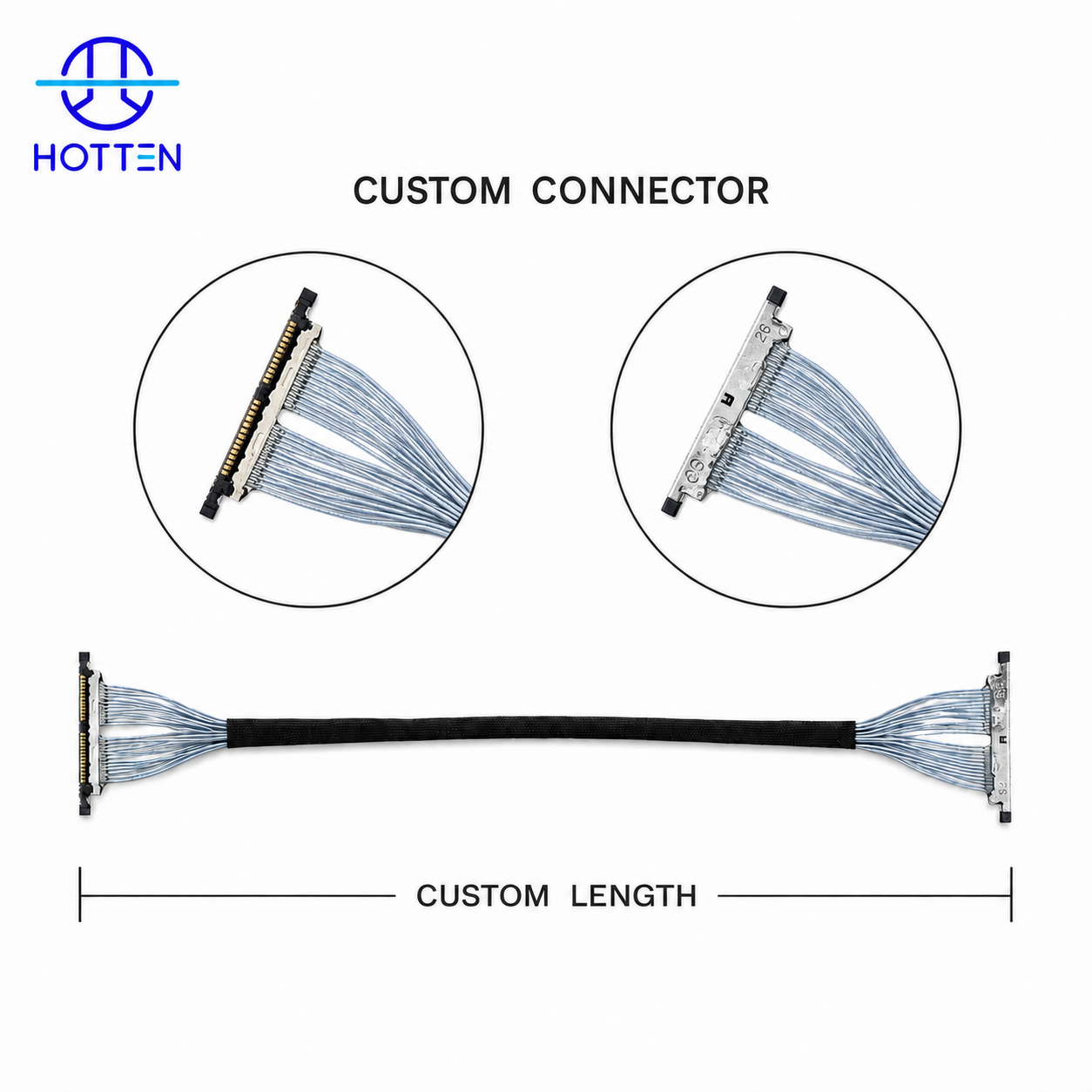
For customized medical cable assemblies, HOTTEN currently supports connector and termination customization alongside cable dimensions and construction.
Different medical applications create different engineering priorities.
Signal Transmission + Channel Density + Low Capacitance + Flexibility
If → the cable connects an ultrasound probe with many signal channels
Then → evaluate multi-core micro coaxial construction, capacitance, impedance and bending requirements together
Why → the probe cable is simultaneously an electrical and mechanical component.
Miniaturization + Imaging Signals + Flexibility + Routing
If → the cable must pass through a highly constrained endoscopic structure
Then → evaluate cable OD, signal integrity, bending behavior and termination dimensions together
Why → space and movement constraints can strongly influence cable construction.
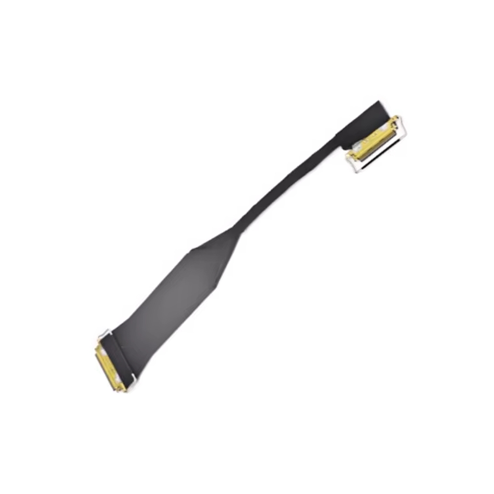
See Endoscope Cable.
High-Frequency Ultrasound + High Channel Density + Small Diameter
If → the system requires many imaging channels in a compact catheter or probe structure
Then → evaluate multi-core micro coaxial architecture and electrical consistency
Why → the cable must support high-density signal transmission within strict dimensional constraints.
See ICE Cable.
Simply requesting:
“High-frequency medical coaxial cable”
does not provide enough information for engineering selection.
A useful RFQ should include:
| Requirement | Recommended Information |
|---|---|
| Signal type | Ultrasound / RF / imaging / high-speed data |
| Frequency | Operating frequency range |
| Impedance | 50Ω / 75Ω / other |
| Attenuation | Maximum acceptable value |
| Capacitance | Target or allowable range |
| Channel count | Number of coaxial cores |
| Conductor | Material / AWG / construction |
| Shielding | Required structure / performance |
| Cable OD | Maximum allowable diameter |
| Flexibility | Static / dynamic |
| Bend requirement | Radius / flex-life if known |
| Cable length | Nominal length + tolerance |
| Connector | Manufacturer / part number |
| Pinout | Required configuration |
| Termination | Required termination method |
| Environment | Temperature / humidity / chemicals |
| Sterilization | Method and cycle requirement if applicable |
| Testing | Electrical + mechanical validation |
| Quantity | Prototype / pilot / mass production |
If → the OEM has a drawing and connector part number
Then → provide them together with the electrical requirements
Why → the supplier can evaluate the cable as a complete assembly rather than selecting a generic coaxial cable.
A practical selection sequence for high-frequency medical cable assemblies is:
Medical Application → Signal Type → Frequency → Impedance → Loss → Capacitance → Channel Count → Cable OD → Shielding → Flexibility → Connector → Validation
For example:
High-density ultrasound application
→ define channel count
→ define signal frequency
→ define impedance
→ determine capacitance requirement
→ determine allowable attenuation
→ define maximum cable OD
→ evaluate micro coaxial structure
→ select shielding
→ define connector and termination
→ validate electrical performance
→ validate bending / handling performance
→ move toward production validation.
This avoids selecting a cable based on a single specification such as AWG, frequency or cable diameter.
How to Choose Micro Coaxial Cable for Ultrasound Probe Applications
Why Low Capacitance Is Critical in Ultrasound Probe Cable Design
Micro-Coaxial Cable Solutions for Medical Ultrasound Imaging Systems
How Coaxial Cable Assemblies Handle High-Frequency Medical Signals
Connector Integrity and Assembly Precision
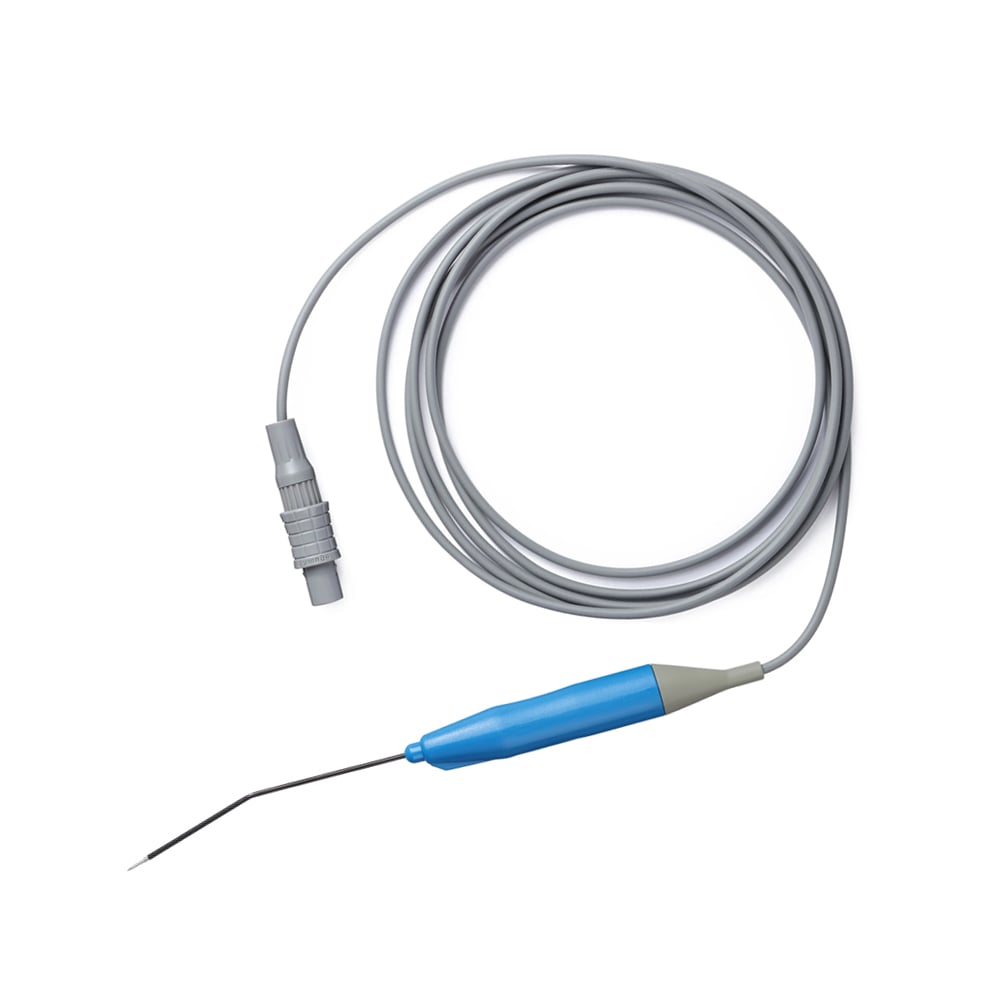
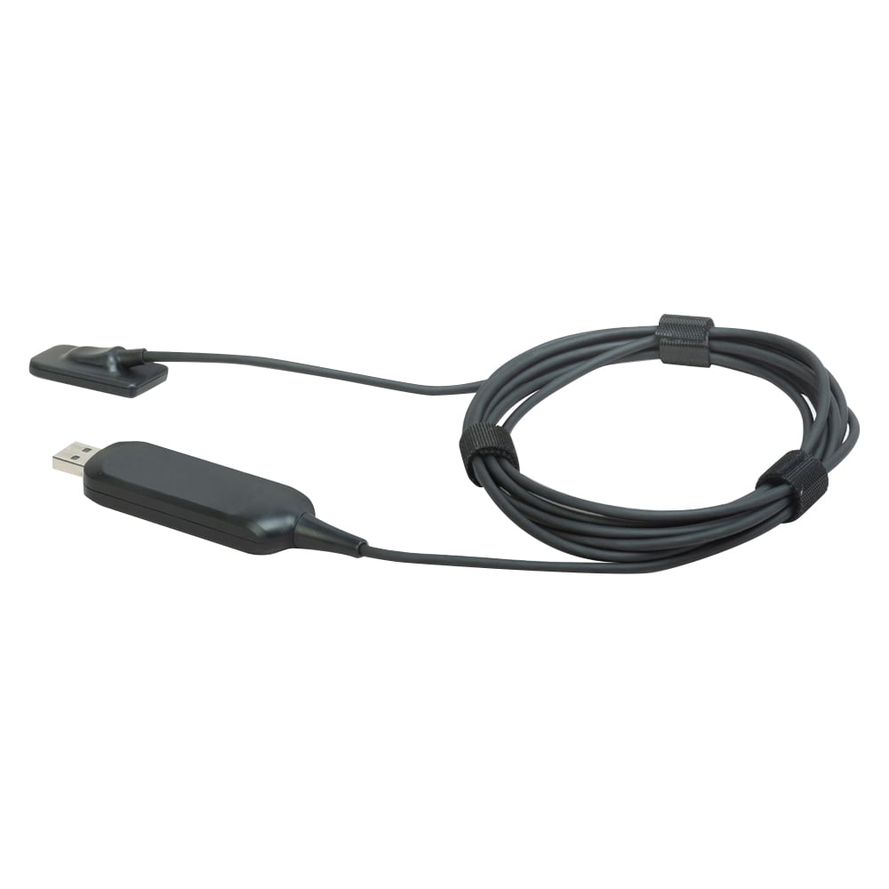
The performance of a coaxial cable assembly depends heavily on the quality of its terminations. The most frequent failure point for high-frequency signals lies at the cable-to-connector interface where poor soldering, improper crimping, or inconsistent dielectric compression can introduce parasitic capacitance and inductance. Hotten's R&D department creates more than 300 new cable specifications each year for use in the company's custom cable assemblies—including Surgical Scalpel Cables and RF Ablation Cables, in which the connector return loss is limited to -20 dB through 6 GHz. Using precision automatic stripping and soldering robots, the exposed conductor length can be controlled consistently across assemblies, andeach assembly undergoes 100% testing for VSWR(Voltage Standing Wave Ratio) and insertion loss using vector network analyzers. At the same time, we strive to balance high performance with cost-effective manufacturing for disposable medical cables, including EEG Lead Wires and Dental Sensing Cables, while maintaining the mechanical and electrical integrity and performance of the cable throughout its intended service life.
Conclusion
Coaxial cable assemblies are much more than just passive connectors; they play a critical role in maintaining signal integrity in high-frequency medical imaging systems. Through the capabilities of shielding, impedance control, loss minimization and connector precision, Hotten's cable engineering helps provide a reliable transmission path for mission-critical medical data. We have more than 40 production units and are producing more than 144 million meters each year, supporting consistent, scalable production across a wide range of cable assemblies from IVUS to medical visualization in AR/VR. For medical OEMs, the goal is to maintain a stable and predictable signal path from the transducer to the imaging electronics.
 Hot News
2026-09-17
2026-09-04
2025-12-17
2025-12-11
2025-12-05