 EN
Quick Links

Home > News > Company news
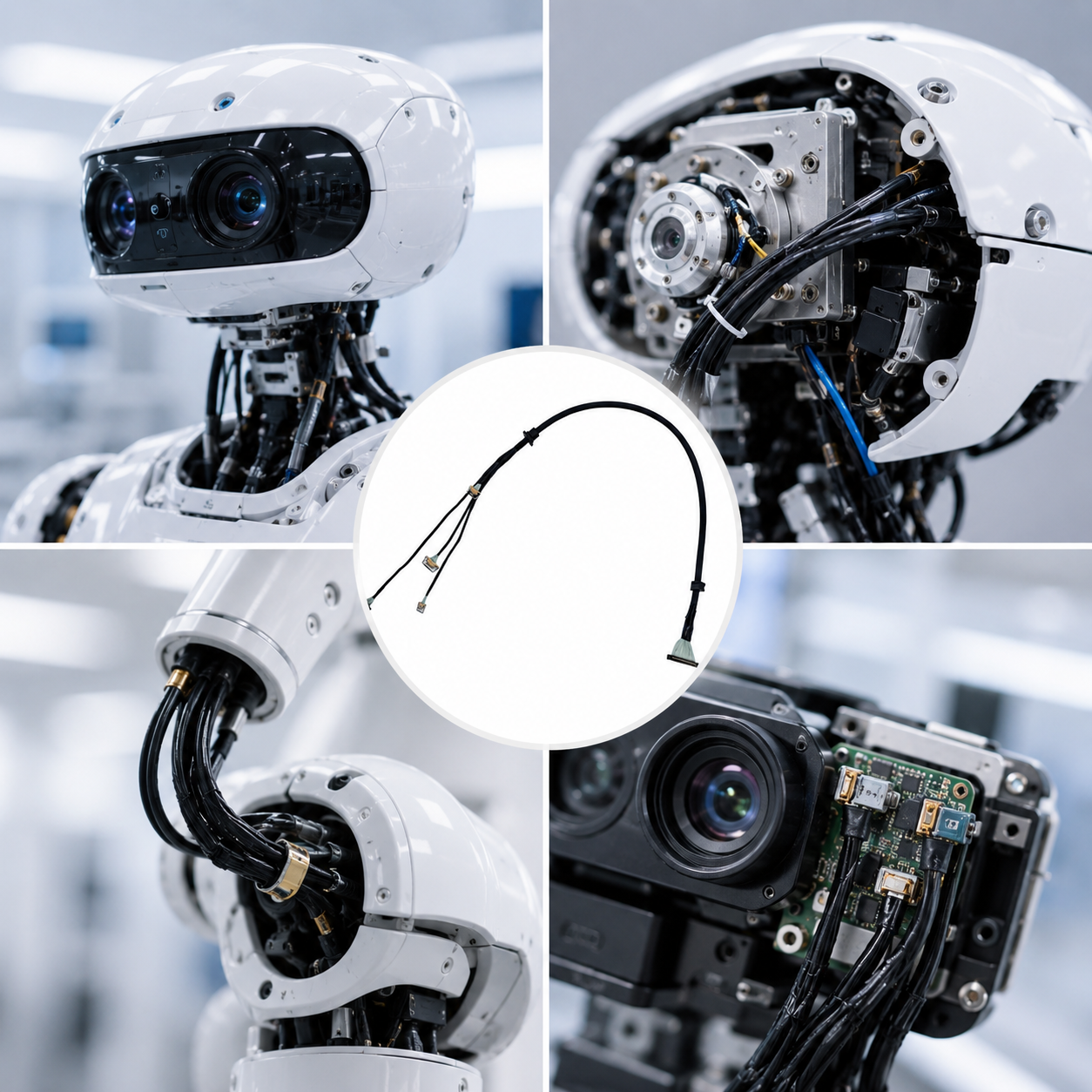
Humanoid robot vision systems may require high-density micro-coaxial cable assemblies when multiple camera modules must be connected through very limited internal space while maintaining high-speed signal transmission, flexible routing, and electromagnetic interference (EMI) control.
If multiple cameras must share a compact routing path inside the robot head → a high-density micro-coaxial cable assembly can consolidate multiple signal channels within a small footprint → while allowing branch routing to different camera positions.
If the cable passes through narrow or moving structures → evaluate conductor size, cable OD, flexibility, shielding, bend radius, and connector geometry together → because the cable must fit the mechanical architecture without creating excessive stress at the interface. For related ultra-fine conductor considerations, see How Does AWG Affect Micro Coaxial Cable Performance?.
If high-speed camera signals are routed near motors, power modules, or communication electronics → evaluate individual shielding, impedance, attenuation, connector transitions, and routing conditions together → then validate the complete cable assembly. For related high-frequency design considerations, see Why Ultra-Fine High-Frequency Coaxial Cable Design Is So Difficult.
For compact high-density interconnect requirements, see HOTTEN's Micro Coaxial Cable Assembly and Robotics Wire Harness products.
For broader application requirements, see HOTTEN's UAV & Robotics and AI & Smart Electronics solutions.
In a recent humanoid robot development project, the customer required a compact cable assembly for the robot’s head-mounted vision system to connect multiple camera modules.
The vision system integrates several cameras with different viewing angles for facial perception, environmental recognition, and motion tracking. Since the robot head must also accommodate servo mechanisms, speakers, structural components, and the main control electronics, the available routing space for the cable assembly was extremely limited.
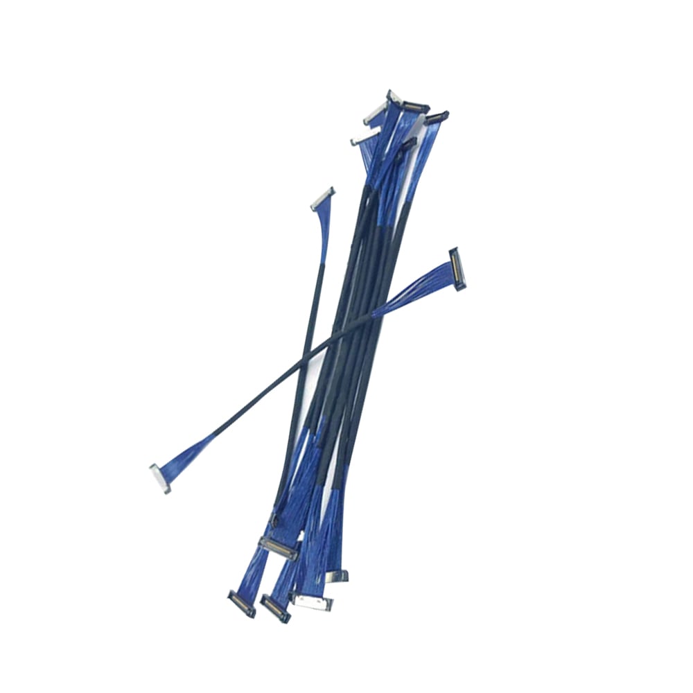
To meet these requirements, the project adopted a custom 50-pin ultra-flexible micro-coaxial cable assembly based on AWG42 ultra-fine micro-coaxial cables, a 0.4 mm pitch I-PEX connector, and a multi-branch cable design, enabling reliable high-speed signal transmission between multiple camera modules and the main controller.
Challenge 1: Extremely Limited Installation Space Inside the Robot Head
The interior of a humanoid robot head typically integrates cameras, servo actuators, audio components, and structural supports, leaving very limited space for cable routing.
In this project, the main cable assembly had to pass through narrow internal channels and branch out at designated locations to connect multiple camera modules. Conventional cable assemblies were too bulky for the available space.
Therefore, flexibility and compact dimensions became critical design priorities.
The AWG42 micro-coaxial cable offers an ultra-small outer diameter and exceptional flexibility, significantly reducing the overall cable size while maintaining excellent signal transmission performance. By using individually shielded conductors instead of an overall shield, the cable achieves a smaller bending radius, allowing flexible routing through complex internal structures while minimizing mechanical stress on the connector interface.
Challenge 2: High-Density Signal Transmission for Multiple Camera Modules
The vision system incorporates multiple camera modules, each requiring an independent high-speed signal channel while minimizing PCB interface usage.
To achieve high-density connectivity, a 50-pin interface was selected.
The 0.4 mm pitch I-PEX connector provides sufficient contact density within an extremely compact PCB footprint, enabling multiple high-speed signal channels to be consolidated into a single connector.
The final cable assembly includes:
• One 50-pin main connector
• Multiple camera branch cables
• Individual terminal connectors for each camera
• Optimized branch layout based on camera installation positions
Challenge 3: Signal Integrity and EMI Control in a Compact Layout
As camera resolutions and data transmission speeds continue to increase, maintaining signal integrity has become a critical requirement.
Inside a humanoid robot, cable assemblies are typically routed close to motors, power modules, and communication circuits, all of which generate electromagnetic interference (EMI).
Micro-coaxial cable technology provides significant advantages in such environments.
Each AWG42 micro-coaxial conductor features its own individual shielding layer, effectively minimizing external EMI and ensuring stable high-speed signal transmission.
The humanoid robot case above illustrates a broader engineering principle: cable architecture should be selected according to the combination of space constraints, camera count, signal requirements, mechanical movement, connector density, and EMI environment.
If several camera modules must be connected within a confined robot head or compact mechanical structure → evaluate a high-density cable architecture first → then determine the required core count, cable OD, branch structure, and connector configuration.
A conventional harness may consume too much routing space when multiple independent high-speed signal paths must pass through narrow internal channels. A customized micro-coaxial assembly can be considered when signal density and physical space are both critical.
For related high-density applications, see Micro Coaxial Cable Assembly.
If camera data is transmitted near motors, power electronics, or communication modules → evaluate shielding, impedance, attenuation, connector transitions, and routing conditions together → then validate the complete signal path.
Individual shielding can help isolate signal paths in compact assemblies, but the connector and termination areas should also be considered as part of the overall EMI and signal-integrity design.
For related impedance-control considerations, see The Importance of Impedance Consistency in Ultra-Fine AWG Micro Coaxial Cables.
If the cable must pass through narrow channels and connect to multiple camera positions → evaluate cable flexibility, branch geometry, connector pitch, termination method, and strain relief together → then validate the assembly under the expected routing conditions.
Reducing cable diameter alone is not enough. The complete assembly must still be practical to route, terminate, secure, and maintain without excessive mechanical stress on the connectors.
For related compact moving applications, see HOTTEN's Robotics Wire Harness and Gimbal Camera Wire Harness solutions.
The choice of AWG should be made as part of the complete cable architecture.
If the available routing space is extremely limited → evaluate finer AWG constructions → then verify resistance, attenuation, flexibility, shielding, termination, and manufacturing consistency.
The finest available conductor is not automatically the correct choice. The final decision depends on the signal requirements and the mechanical and manufacturing conditions of the complete assembly.
For related conductor-size considerations, see How Does AWG Affect Micro Coaxial Cable Performance?.
If multiple camera modules are installed at different positions → evaluate a custom multi-branch architecture → then optimize branch length, routing direction, connector locations, and cable support according to the robot structure.
A multi-branch design can reduce the need for multiple separate cable routes, but the branch points must be designed carefully to avoid excessive bending or mechanical stress.
The actual configuration should therefore be based on the robot's mechanical drawings and camera installation positions.
For a project similar to this case, an engineering or procurement team should provide:
| Requirement | Information to Confirm |
|---|---|
| Application | Humanoid robot vision, machine vision, camera module |
| Camera Count | Number of camera connections |
| Signal | Video/data type, frequency or data-rate requirements |
| Conductor | AWG, core count, cable construction |
| Dimensions | Maximum cable OD and available routing space |
| Connector | Manufacturer, part number, pitch, pinout |
| Branching | Number of branches and branch locations |
| Mechanical | Bend radius, flex movement, torsion, strain relief |
| Shielding | Individual shielding / overall shielding requirements |
| Length | Main cable and branch lengths |
| Environment | Temperature, vibration and other conditions |
| Validation | Electrical, dimensional and mechanical testing |
| Production | Prototype quantity and expected production volume |
Providing drawings, connector part numbers, pinouts, camera locations, and routing constraints can significantly improve the accuracy of the initial engineering evaluation.
The practical decision can be summarized as:
If the robot vision system has multiple high-speed cameras in a confined space → evaluate high-density micro-coaxial architecture → then optimize AWG, shielding, branch structure, and connector pitch.
If the cable must move with a camera or robotic mechanism → evaluate flexible cable construction and routing geometry → then validate flex life and termination reliability.
If the cable runs near motors and power electronics → evaluate individual shielding and signal-integrity requirements → then validate the complete cable and connector system.
If the assembly contains many branches and miniature connectors → evaluate manufacturability and termination feasibility at the beginning of the design → then proceed to prototype validation.
For broader robotics applications, see HOTTEN's Robotics Wire Harness.
For AI-related compact high-speed interconnects, see AI & Smart Electronics.
For customized micro-coaxial assemblies, see Micro Coaxial Cable Assembly.
The practical development sequence is:
Robot architecture → camera count → signal requirements → routing space → cable architecture → AWG / shielding → connector → branch design → prototype → validation → production
The final cable assembly utilizes AWG42 ultra-fine micro-coaxial cable, a 0.4 mm pitch I-PEX connector, and a customized multi-branch cable architecture.
Key features include:
• 50-pin high-density connector interface
• AWG42 ultra-flexible micro-coaxial construction
• Multi-camera branch output design
• Individually shielded signal lines
• Custom cable lengths based on robot structure
• Compact connector design
• Optimized routing solution for confined spaces
At Hotten Cable, our engineering support process includes:
• Drawing review and connector verification
• Cable routing feasibility evaluation
• Design for Manufacturability (DFM) analysis
• Signal integrity and cable structure assessment
• Rapid quotation support
• Fast engineering drawing generation
• Prototype manufacturing and validation
• Low-volume production support
Humanoid robot vision systems place increasingly demanding requirements on cable assembly design. Limited installation space, multiple camera connections, and high-speed data transmission often require highly customized cable solutions rather than standard off-the-shelf products.
At Hotten Cable, we specialize in developing custom micro-coaxial cable assemblies tailored for advanced robotics, machine vision, medical devices, industrial automation, and other compact high-speed interconnect applications.
 Hot News
2026-09-17
2026-09-04
2025-12-17
2025-12-11
2025-12-05