 EN
Quick Links

Home > News > Company news
40-pin 20454-series to 30-pin DF14-series configuration
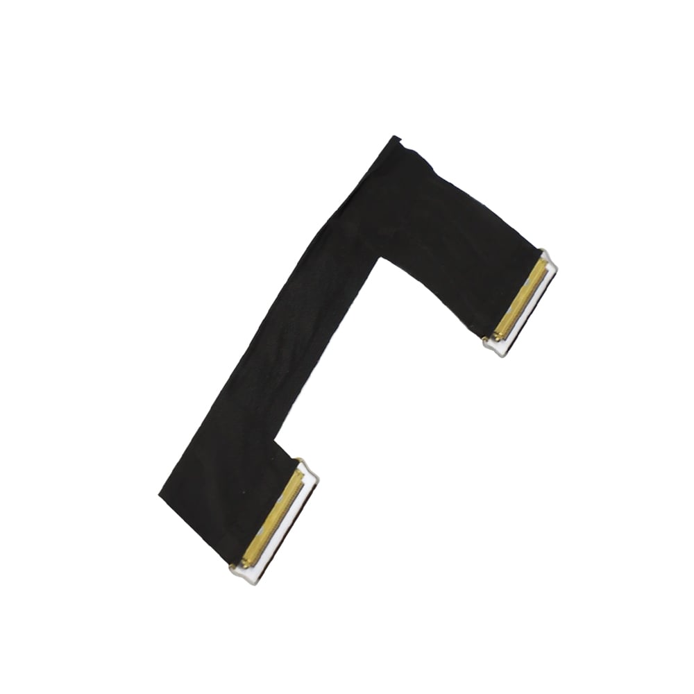
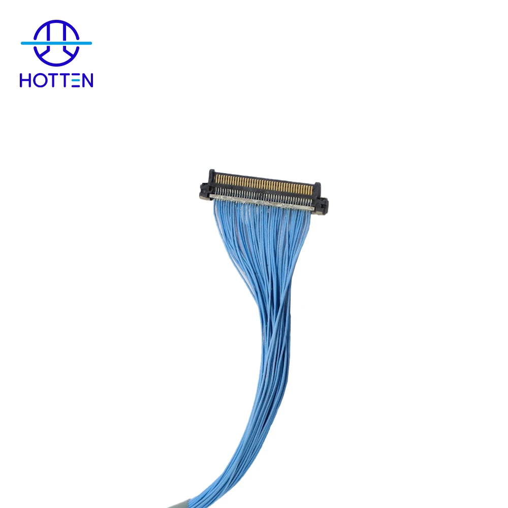
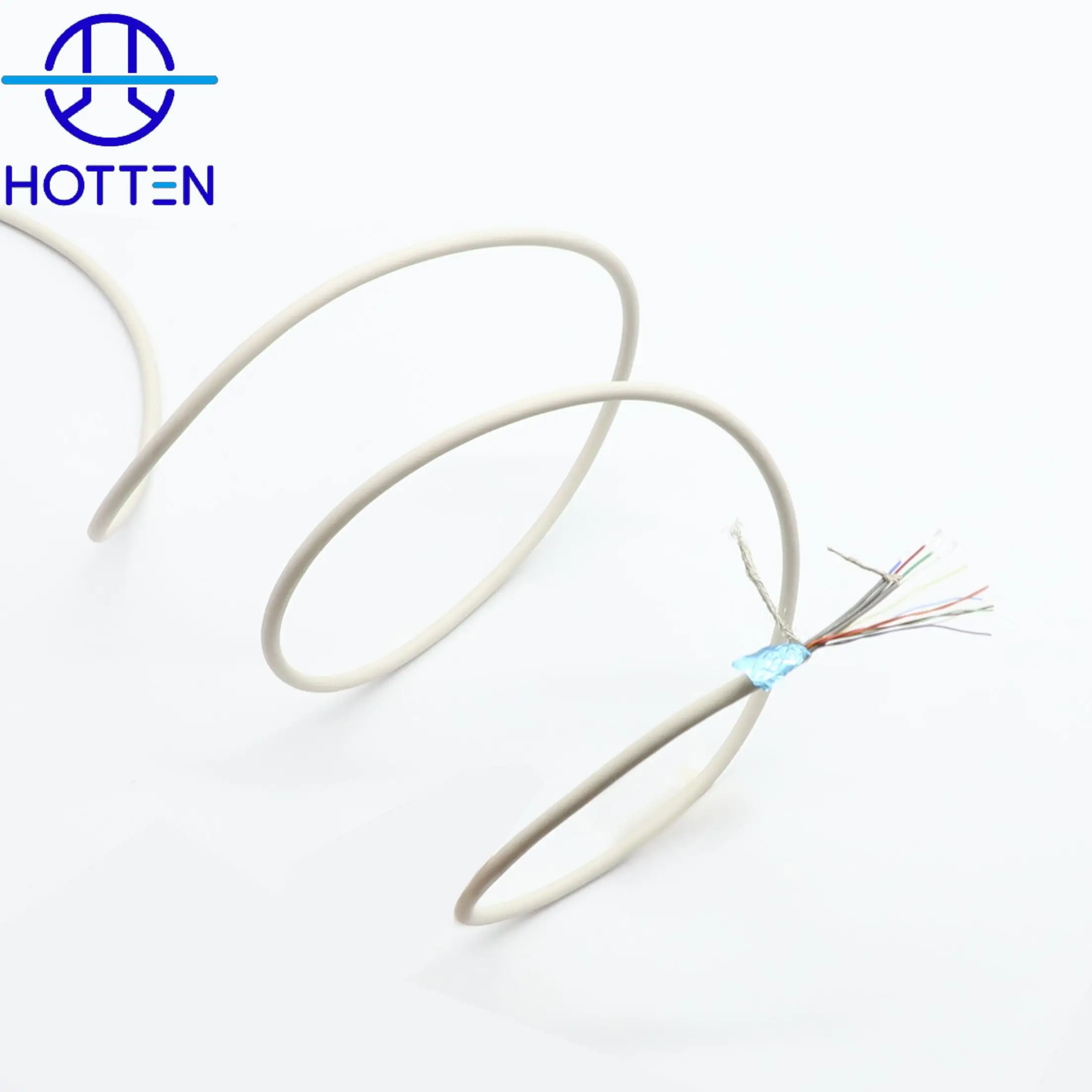
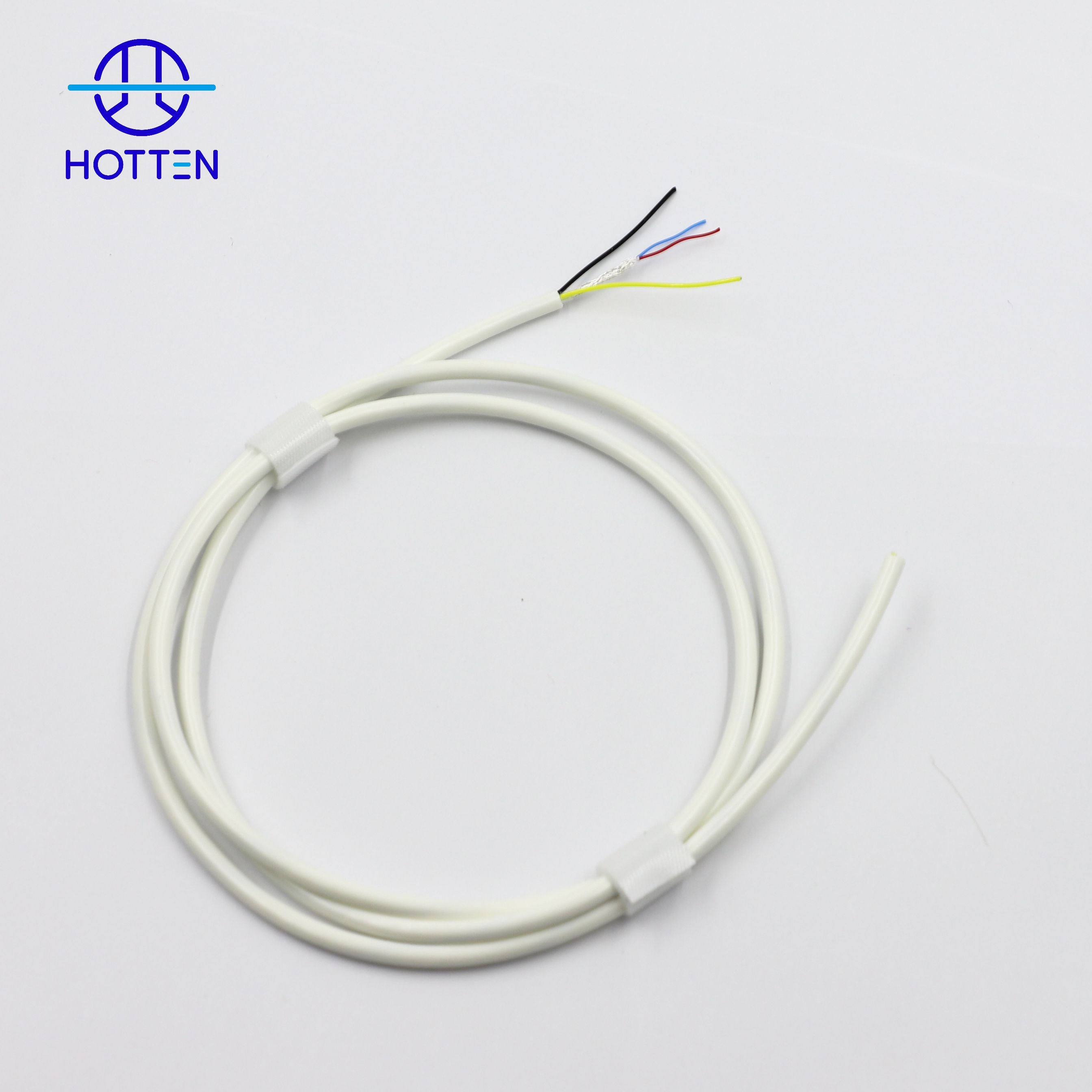
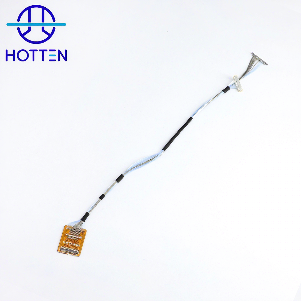
Hotten developed a custom LVDS data cable assembly for a German customer, with the connector configuration, wiring and construction defined by the project drawing. The design combines a 40-position 20454-series interface with a 30-position DF14-series interface, using UL 10064 32AWG wire and a specified length of 250 ± 5 mm.
This project illustrates how Hotten translates a customer drawing into specific assembly and inspection requirements, covering pin mapping, paired wiring, conductive wrapping and connector-end reinforcement.
Project specifications
Parameter |
Project requirement |
Application |
LVDS signal transmission |
P1 connector reference |
I-PEX 20454-040T, 40 positions; equivalent specified |
P2 housing reference |
HRS DF14-30S-1.25C, 30 positions; equivalent specified |
P2 terminal reference |
HRS DF14-2628SCF, tin plated; equivalent specified |
Wire |
UL 10064, 32AWG |
Specified length |
250 ± 5 mm, measured between drawing datums |
Paired wiring |
Five blue-and-white twisted pairs shown in the pin map |
Wrapping |
Inner conductive tape and outer black acetate tape |
Connector-end treatment |
Conductive fabric overlapped onto the P1 metal shell; UV adhesive at the root |
Electrical inspection |
100% open-circuit, short-circuit and miswiring testing required |
Connector references and equivalent-component requirements follow the project bill of materials.
Custom pin mapping between different interfaces
The 40-position and 30-position connector housings do not represent a one-to-one, fully populated connection. The approved configuration includes unused positions, individual wire connections and multiple wires joined to selected terminals. Five blue-and-white twisted pairs are identified in the pin map, alongside separate conductors.
For Hotten, this makes the pin map a central production reference. Connector orientation, pin numbering, wire colour and pair assignment must be read together. Both connector contact faces are shown facing upward in the drawing, establishing the orientation used to interpret the wiring. Assembly inspection must follow this defined mapping rather than assume that corresponding pin numbers connect directly.
Conductive wrapping and connector-end reinforcement
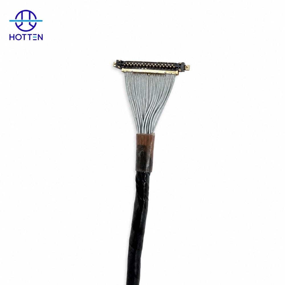
The cable body is specified with an inner conductive layer and an outer black acetate-tape wrap. At the P1 end, conductive fabric overlaps the metal shell, and UV adhesive secures the connector root. These details define the assembly construction and the intended conductive connection to the shell.
The drawing also controls the exposed wire layout at both ends. Wires must lie evenly without bunching, distortion or excessive loading on individual conductors. Tape terminations must remain secure, and connector pins and bodies must be free of contamination, damage, heat marks and deformation. These workmanship requirements give production and inspection teams concrete acceptance criteria.
Electrical inspection defined by the drawing
The project specifies 100% open-circuit, short-circuit and miswiring testing. Additional electrical requirements are a maximum continuity resistance of 5 Ω and a minimum insulation resistance of 10 MΩ at DC 200 V. These values are drawing acceptance criteria, rather than reported measurement results.
Inspection is therefore tied to the specified wiring configuration as well as the electrical limits. This provides a defined basis for checking connection integrity and insulation before acceptance.
Drawing-based LVDS cable customization with Hotten
This German customer project demonstrates Hotten’s approach to drawing-based cable assembly: define the connector interfaces, translate the pin map into wiring requirements, control wrapping and end treatment, and align inspection with the specified electrical and workmanship criteria.
For a similar custom LVDS cable, send Hotten the connector references or mating-interface drawings, pin map, required length and tolerance, routing constraints, and electrical test requirements. These inputs provide the basis for reviewing the cable configuration and agreeing the assembly specification.
 Hot News
2026-09-17
2026-09-04
2025-12-17
2025-12-11
2025-12-05