Home > News > Company news
Technical analysis for OEM engineers covering cable structure, shielding, impedance control, material selection, and reliability validation in high-performance cable assembly applications.
In advanced ultrasound imaging systems, the interconnect network is directly connected to high-impedance, microvolt-level piezoelectric transducers. These front-end components are extremely sensitive to signal loss and electrical noise. When signals travel through dense 64-, 128-, 160-, 192-, and 256-channel array topologies, the distributed capacitance of the ultrasound probe cable acts as a parasitic low-pass filter shunt. Excessive cable capacitance directly degrades the signal before it reaches the beamforming system. Therefore, minimizing capacitance throughout the custom cable assembly is essential for maintaining signal-to-noise ratio (SNR) and achieving sub-millimeter axial and lateral spatial resolution.
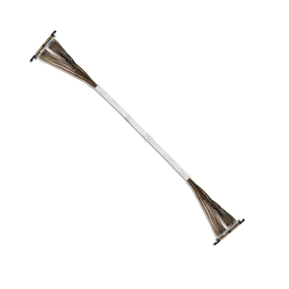
Capacitance is directly determined by the physical geometry and dielectric properties of the insulation system. In coaxial cable structures, capacitance is proportional to the relative dielectric constant (εr) of the insulating material. Standard solid fluoropolymers such as FEP and PFA typically exhibit a dielectric constant of approximately 2.1. By utilizing microcellular gas-injection foaming technology to produce foamed PFA or FEP insulation, air voids (εr = 1.0) are introduced into the dielectric structure, reducing the overall dielectric constant to approximately 1.4–1.6. This approach enables ultra-fine micro coaxial cable constructions ranging from 40AWG to 48AWG to achieve target capacitance values as low as 50 pF/m.
Typical Distributed Capacitance Comparison:
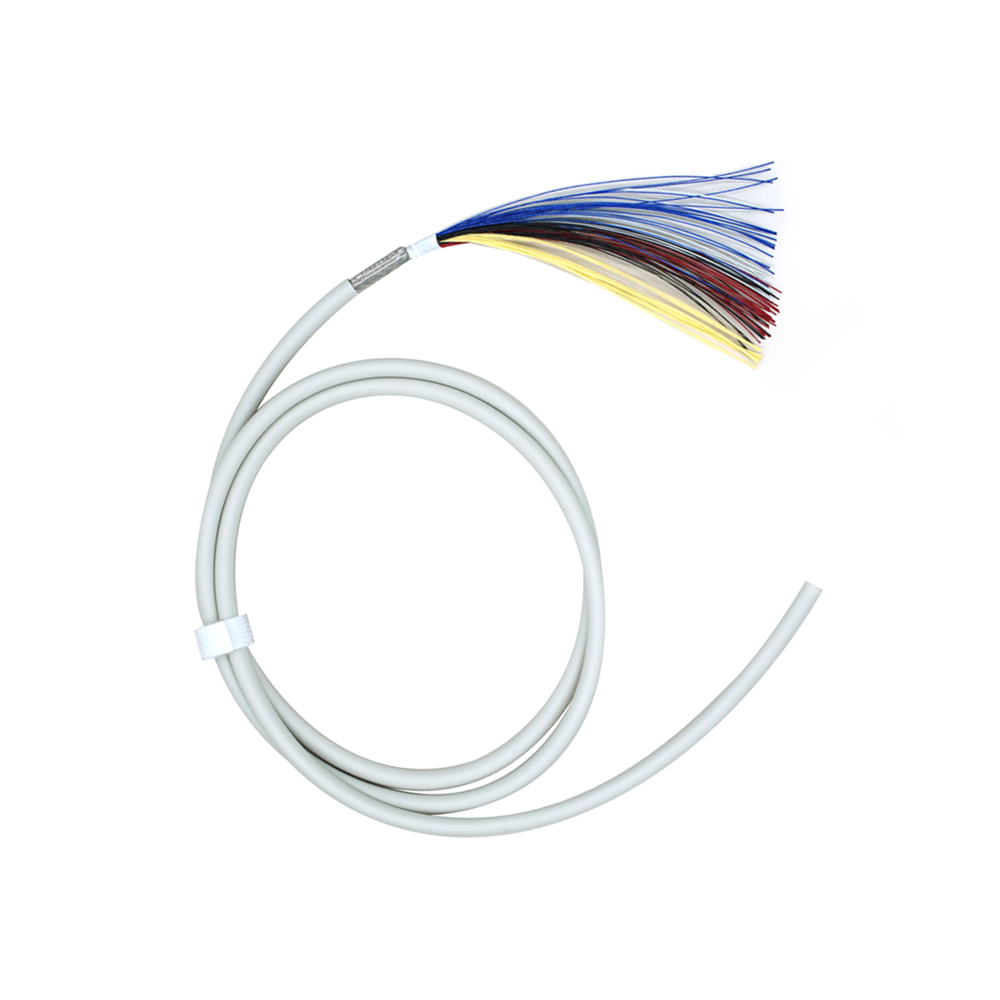
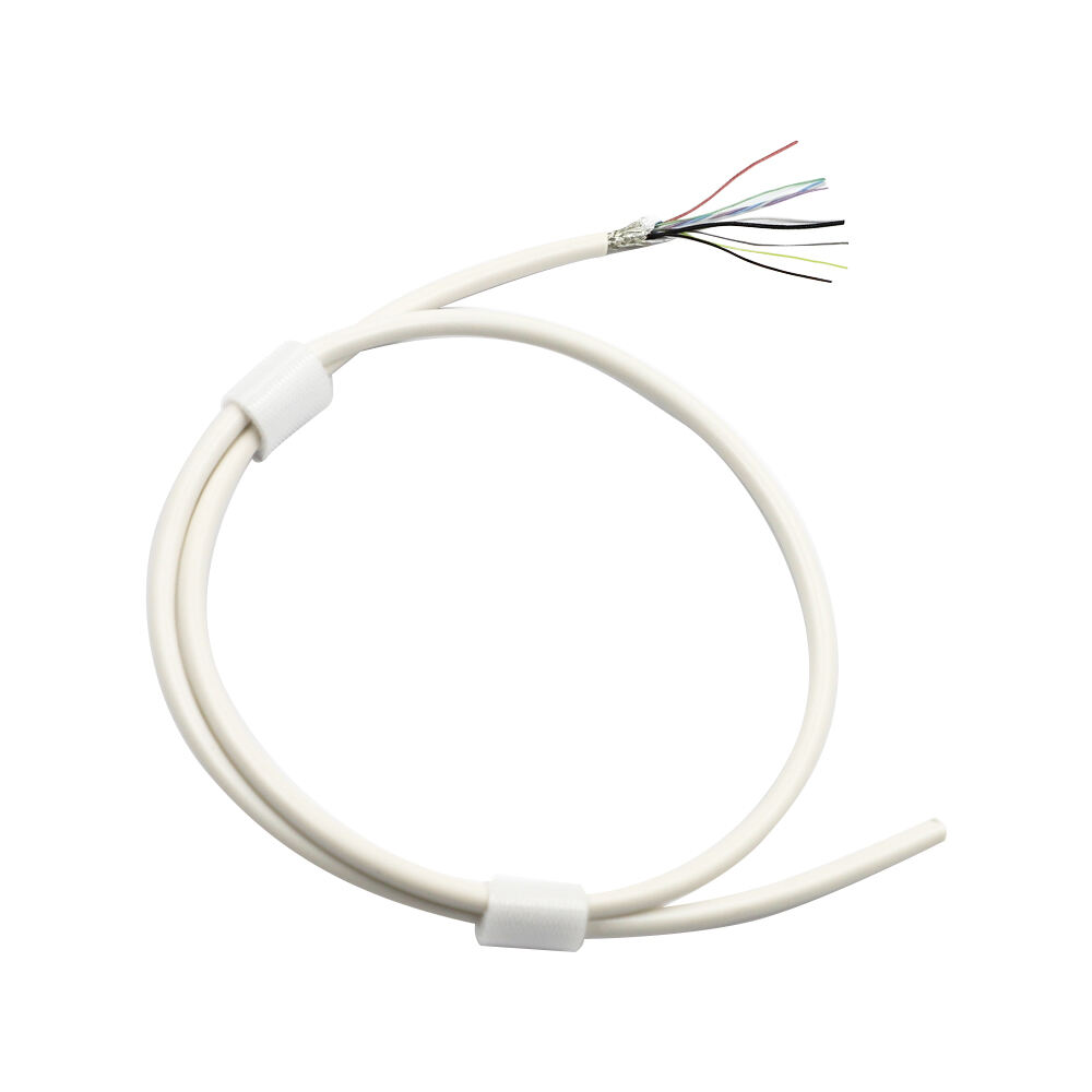
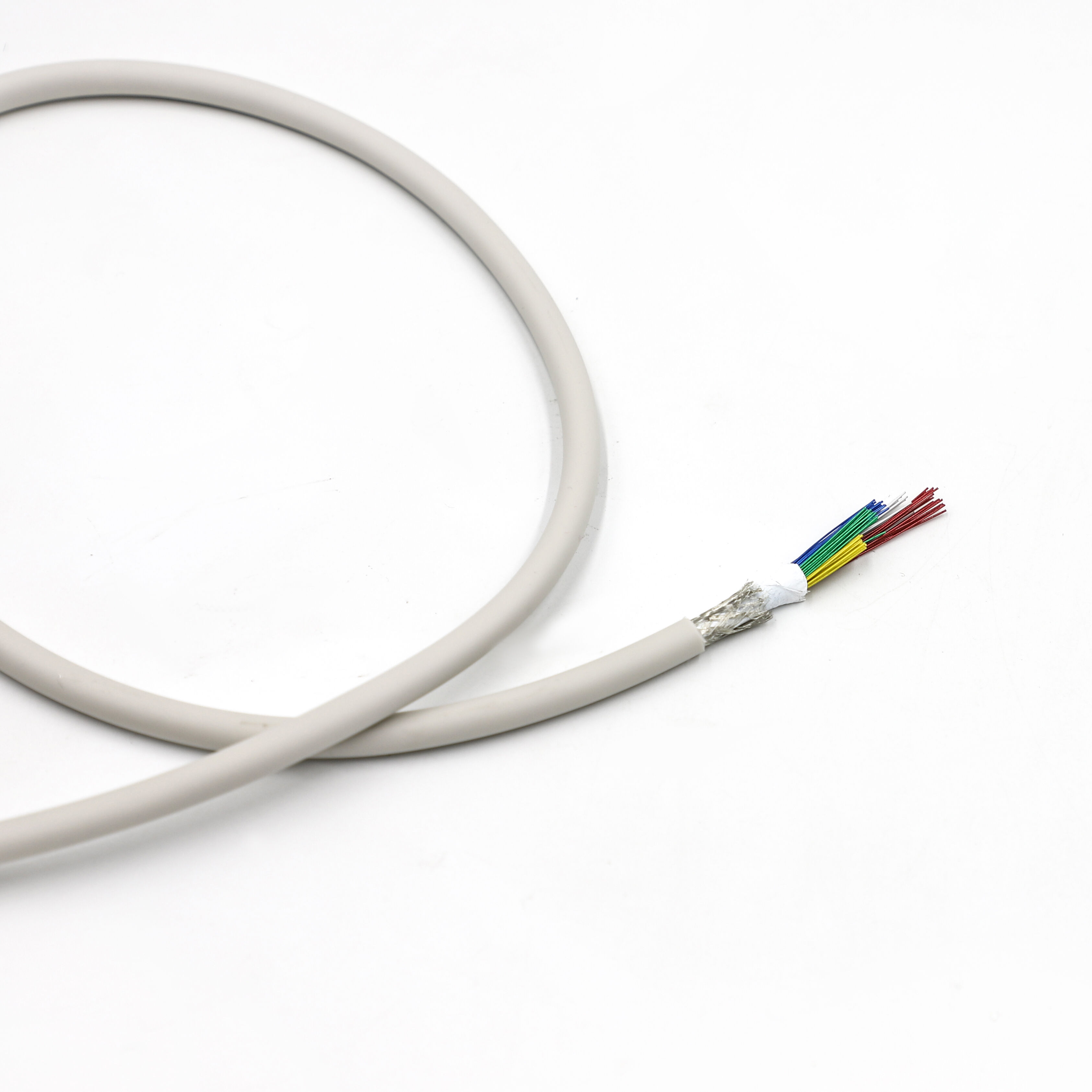
Multi-channel probe systems require highly uniform impedance-controlled cable architectures to eliminate channel skew and phase mismatch. Even minor variations in concentricity or foam density can compromise electrical consistency and introduce destructive phase errors. At the same time, the dense arrangement of micro coaxial cables requires advanced EMI shielding strategies. Combining served-wire shielding with overall shield constructions provides the isolation necessary to reduce external electromagnetic interference and internal crosstalk, thereby preserving signal integrity.
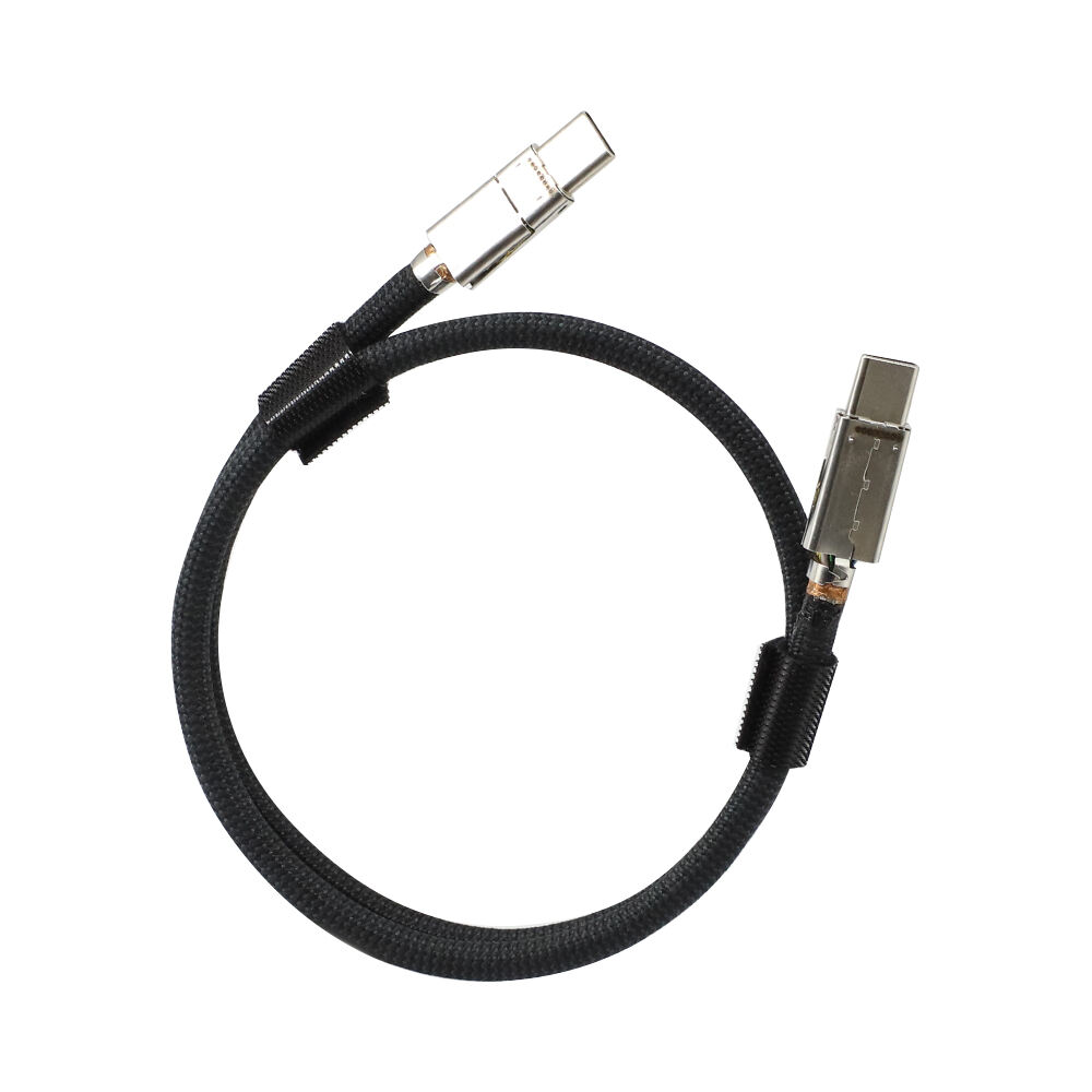
Medical imaging applications require high-flex cables capable of withstanding tens of thousands of bending and torsion cycles encountered during clinical operation. However, reducing capacitance through thicker insulation layers or increasing shielding robustness inevitably increases cable stiffness and overall diameter. To balance this engineering trade-off, high-strength silver-plated copper alloy conductors and highly flexible jacket materials are commonly specified. Their performance must be validated through rigorous multi-axis flexing and bend-reliability testing.
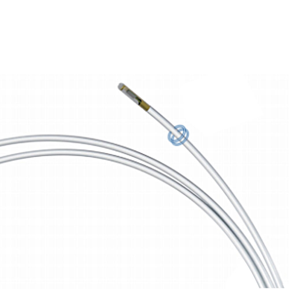
The termination interface between the micro coaxial cable bundle and the system PCB is a common source of impedance discontinuity. Terminating ultra-fine conductors as small as 48AWG requires high-density direct soldering techniques or micro coaxial connectors with pitches as small as 0.3 mm. Abrupt geometric transitions at these interfaces can generate signal reflections that negatively affect imaging consistency across channels.
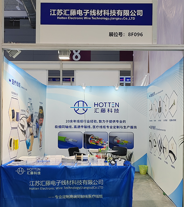
Producing high-yield medical cable assemblies requires strict control of wire drawing, fluoropolymer extrusion foaming, and multi-axis planetary cabling processes to ensure uniform tension distribution without introducing torsional stress. Manufacturing should be conducted in ISO 13485-certified facilities. Comprehensive quality assurance procedures include 100% capacitance testing to map the impedance profile along every channel and verify the absence of localized manufacturing deviations.
In a 128-channel high-frequency linear-array probe designed for superficial vascular imaging, replacing a standard solid-dielectric cable bundle with a custom 50 pF/m foamed-dielectric assembly can significantly reduce high-frequency insertion loss over a 2-meter cable length. The reduction in capacitive loading directly improves Doppler sensitivity and overall clinical image clarity.
Optimizing advanced ultrasound probes requires controlling distributed capacitance to a target threshold of approximately 50 pF/m through precision foaming technology and tightly controlled manufacturing tolerances. For OEM engineering teams, selecting an interconnect partner with specialized micro coaxial extrusion capabilities and ISO 13485 manufacturing infrastructure ensures that theoretical signal-integrity advantages translate into repeatable, real-world clinical performance.
 Hot News
2025-12-17
2025-12-11
2025-12-05
2025-04-29