 EN
EN
Quick Links

Modern camera and imaging systems often need to transmit high-speed signals through very limited physical space. As cameras become smaller and systems integrate more channels, the cable assembly must fit tighter routing paths without compromising the required electrical and mechanical performance.
This is where micro coaxial cable assemblies can provide an important interconnect solution.
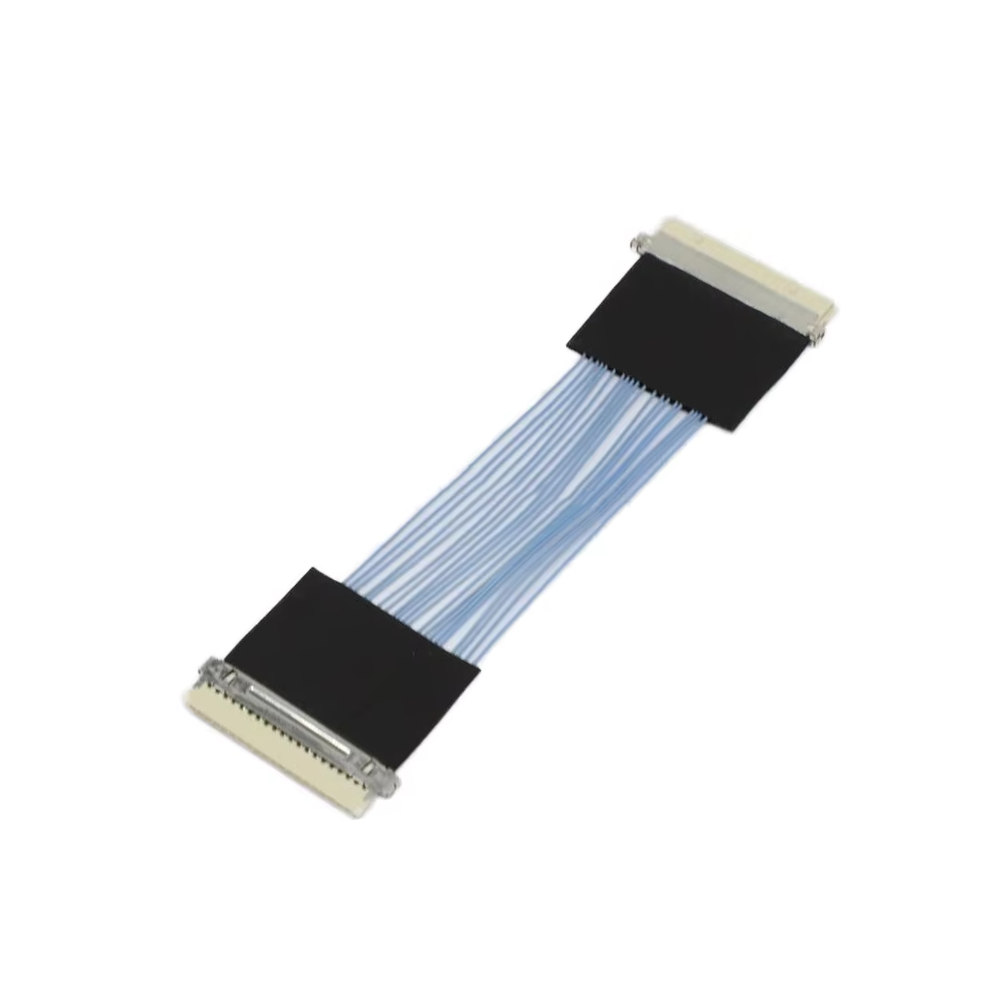
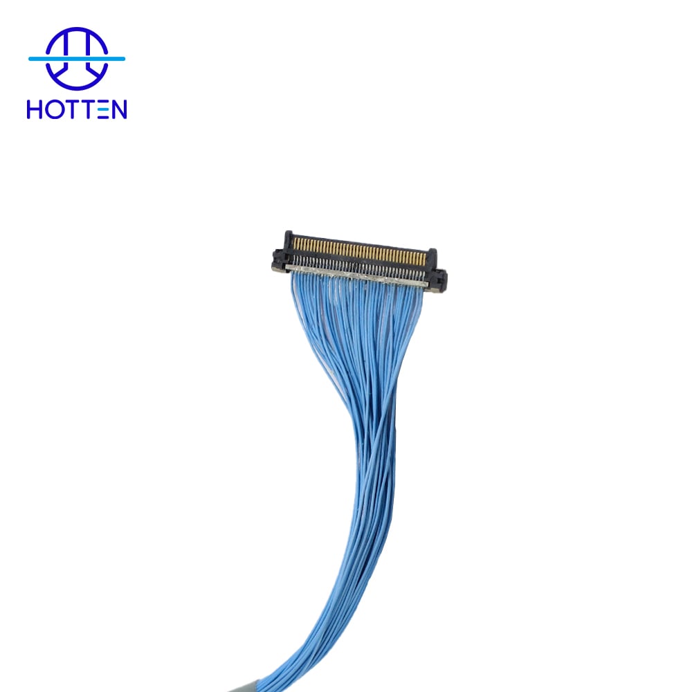
A micro coaxial cable assembly combines miniature coaxial cables with connectors and terminations designed for a specific application. Compared with larger conventional cable constructions, micro coaxial assemblies can help OEM engineers manage space constraints, high channel density, signal transmission requirements and complex internal routing.
These requirements can be found in medical imaging equipment, compact cameras, UAV and gimbal systems, robotics, AI hardware and other high-density electronic devices.
A micro coaxial cable assembly is a finished interconnect consisting of one or more small-diameter coaxial cables terminated with specified connectors or interfaces.
A typical assembly may include:
Micro Coaxial Cable + Connector + Termination + Strain Relief
The cable itself provides the electrical transmission path, while the connector and termination provide the interface between the cable and the electronic system.
For OEM applications, the complete assembly is often more important than the cable alone because the available space, connector configuration, pinout, cable length and routing requirements must all work together.
The main reason is high interconnect density within a limited space.
A camera or imaging module may need to accommodate multiple high-speed signal channels while leaving space for sensors, lenses, processing electronics and mechanical structures.
A micro coaxial assembly can help address several engineering requirements:
Small cable diameter
High channel density
Controlled electrical characteristics
Flexible internal routing
Compact connector interfaces
Shielding between signal paths
Customized cable lengths and configurations
The exact benefits depend on the cable construction and system requirements.
Space is often one of the first limitations engineers encounter when designing compact electronic equipment.
Traditional larger cables may occupy too much space when multiple signal channels need to be routed through the same area.
Micro coaxial cables provide a smaller individual signal path, allowing multiple cables to be arranged within a compact assembly.
This can be particularly useful for:
Camera modules
Medical imaging systems
Endoscopic imaging equipment
UAV cameras
Gimbal systems
Robotics vision systems
Compact AI hardware
The objective is not simply to make the cable smaller.
The cable still needs to satisfy the electrical, mechanical and manufacturing requirements of the final system.
As imaging systems increase their resolution and processing capabilities, the interconnect may need to handle multiple signal channels.
A high-density assembly can therefore involve many individual micro coaxial cables or a multi-coax configuration terminated into a compact connector.
The design needs to consider:
| Design Factor | Why It Matters |
|---|---|
| Cable diameter | Determines available routing space |
| Number of channels | Affects overall assembly density |
| Connector size | Limits interface space |
| Cable length | Affects routing and electrical characteristics |
| Pinout | Determines signal assignment |
| Shielding | Helps manage electromagnetic coupling |
| Bend radius | Affects mechanical routing |
| Strain relief | Helps protect the termination area |
For OEM projects, these factors should be considered together rather than selecting a cable first and designing the connector interface later.
Camera systems can use high-speed digital interfaces to transfer image data between sensors, processing boards and other electronic modules.
At higher signal rates, the interconnect becomes an increasingly important part of the signal path.
Micro coaxial cable construction can be designed around electrical requirements such as:
Characteristic impedance
Insertion loss
Return loss
Capacitance
Shielding
Electrical length
Crosstalk considerations
The required values depend on the interface and system design.
For this reason, OEM engineers should avoid choosing a micro coaxial cable only according to its outside diameter or conductor size.
A smaller cable is not automatically a better high-speed cable.
The electrical structure has to be compatible with the intended signal transmission requirements.
Multiple high-speed signal channels routed close to each other can create electromagnetic coupling concerns.
Coaxial construction provides a shielded transmission structure around the signal conductor.
Depending on the application, different shielding constructions may be considered, including:
Foil shielding
Braided shielding
Combined foil and braid
Other application-specific constructions
Shielding design should be selected according to the frequency range, mechanical requirements and required electromagnetic performance.
It is also important to consider the connector transition.
A well-designed cable can still experience performance issues if the cable-to-connector transition introduces an electrical discontinuity.
Not every camera cable operates in a fixed position.
UAV cameras, gimbals and robotic vision systems may experience repeated movement during normal operation.
In these applications, engineers may need to consider:
Minimum bend radius
Repeated bending
Twisting
Cable routing
Strain relief
Jacket material
Connector retention
A cable designed for fixed internal routing should not automatically be used in a continuously moving application.
The required mechanical construction should be based on the actual movement profile of the equipment.
For a gimbal or robotic application, the supplier should understand how the cable moves rather than simply receiving a nominal cable length.
Medical imaging systems can combine high channel density, compact mechanical structures and sensitive electronic signals.
Applications may include:
Ultrasound systems
Endoscopic imaging
Surgical imaging equipment
Intravascular imaging systems
Compact diagnostic devices
For these applications, cable requirements can include a combination of:
Small OD + High Channel Density + Signal Integrity + Flexibility + Mechanical Reliability
However, the requirements are different from those of a UAV or camera gimbal.
For example, a reusable medical device may have cleaning or sterilization requirements, while a compact camera module may primarily require space-efficient routing and high-speed signal transmission.
The cable construction should therefore be selected according to the actual application rather than treating all imaging systems as having the same requirements.
One of the most common mistakes in cable assembly design is focusing heavily on the cable while treating the connector as an afterthought.
For high-density applications, connector selection can affect:
Available installation space
Number of signal channels
Pin assignment
Termination method
Mechanical retention
Cable routing
Assembly reliability
For an OEM project, useful connector information includes:
Connector manufacturer
Connector part number
Mating connector
Pin count
Pinout
Contact configuration
Required termination method
Providing the exact connector part number during the quotation process can make engineering evaluation much more efficient.
A standard cable may not fit the mechanical and electrical requirements of a compact imaging system.
OEMs may require customization of:
Cable size
Conductor size
Cable length
Number of coaxial channels
Connector configuration
Pinout
Shielding
Jacket material
Bend requirements
Strain relief
For example, a camera manufacturer may have a defined PCB connector, limited routing space and a fixed cable length.
In this situation, the required solution is not simply a smaller coaxial cable.
It is a custom micro coaxial cable assembly designed around the complete interface.
Providing detailed information at the quotation stage can reduce unnecessary engineering iterations.
A practical RFQ may include:
| Information | Example Requirement |
|---|---|
| Application | Camera, medical imaging, UAV, robotics |
| Cable type | Micro coaxial |
| Number of channels | Required channel count |
| Cable length | Finished assembly length |
| Conductor size | Required AWG if specified |
| Impedance | Target characteristic impedance |
| Connector | Manufacturer and part number |
| Pinout | Signal assignment |
| Shielding | Required construction |
| Bend requirements | Minimum radius or movement profile |
| Jacket | Required material or environmental requirements |
| Electrical performance | Applicable loss or signal requirements |
| Quantity | Prototype and expected production volume |
| Testing | Required electrical and mechanical tests |
If drawings or samples are available, they can also help the cable manufacturer understand the physical constraints of the application.
Although micro coaxial technology is used across multiple industries, the design priorities can be different.
| Application | Typical Cable Design Priorities |
|---|---|
| Medical imaging | High density, flexibility, signal integrity, mechanical reliability |
| Camera modules | Compact size, high-speed signal transmission, connector density |
| UAV / gimbal | Lightweight construction, flexibility, repeated movement |
| Robotics vision | Flexibility, routing, signal integrity, mechanical durability |
| AI hardware | High-density interconnects, high-speed signals, compact routing |
| RF systems | Impedance control, shielding, insertion loss and connector performance |
This is why an experienced supplier should evaluate the application rather than recommend the same micro coaxial construction for every project.
OEM buyers should consider more than the supplier's product catalog.
Useful questions include:
Can the supplier manufacture the required micro coaxial construction?
Can the supplier work with the specified connector?
Can the supplier provide customized cable lengths and channel configurations?
Can the engineering team review drawings or samples?
How is characteristic impedance controlled?
What electrical and mechanical tests are available?
Can the supplier support prototype development?
Can the same supplier support volume production?
How are engineering changes handled?
Can the supplier maintain consistent production between lots?
For a custom cable project, engineering communication can be particularly important because the cable, connector and mechanical routing often need to be considered together.
A reliable cable assembly project usually develops through several stages:
Specification → Prototype → Validation → Pilot Production → Mass Production
During prototype development, the OEM may identify changes to:
Cable length
Connector selection
Pinout
Routing
Shielding
Strain relief
Mechanical dimensions
A supplier capable of supporting these changes can make the transition to production easier.
The objective is not simply to produce a working prototype, but to establish a repeatable construction that can be manufactured consistently at the required production volume.
HOTTEN works with OEM customers on customized micro coaxial cable and cable assembly projects for applications where compact dimensions, high channel density, signal transmission and mechanical requirements need to be considered together.
Depending on the project, the cable solution can be developed around:
Micro coaxial cable
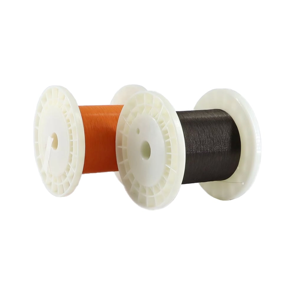
Ultra-fine electronic wire
Multi-channel cable assemblies
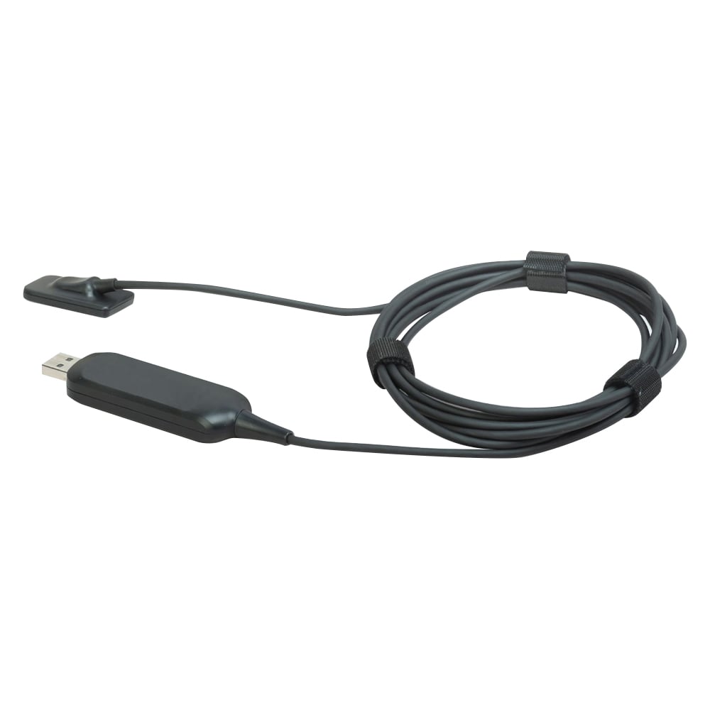
Camera cable assemblies
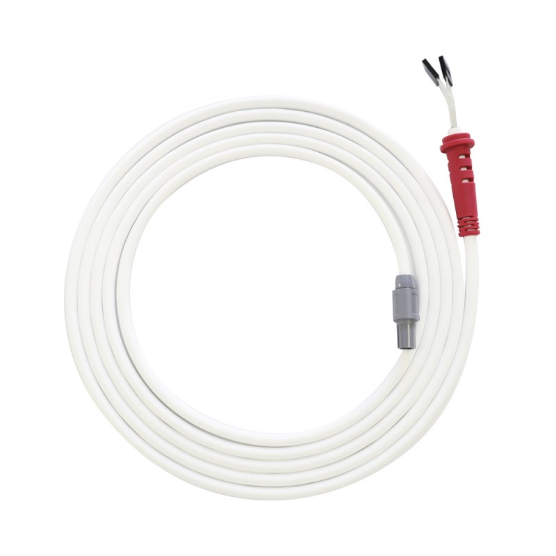
Medical cable assemblies
UAV and gimbal cable assemblies
High-speed cable assemblies
Custom connector termination
OEM customers can provide drawings, samples, connector part numbers or application requirements for engineering evaluation.
For high-density camera and imaging systems, the most suitable cable should be selected based on the complete electrical and mechanical requirements rather than cable diameter alone.
A micro coaxial cable assembly combines one or more small-diameter coaxial cables with connectors and terminations for a specific electronic application.
They can help route multiple signal channels through limited space while providing a controlled coaxial transmission structure suitable for the required electrical performance.
They can be suitable for applications such as ultrasound and other compact imaging systems when the cable construction meets the required electrical, mechanical and environmental requirements.
Yes. Depending on the supplier's manufacturing capability, customization can include cable length, channel configuration, conductor size, shielding, connector type, pinout, jacket and termination.
Useful information includes the application, cable type, number of channels, cable length, impedance, connector part number, pinout, shielding requirements, mechanical constraints and required testing.
No. Cable diameter is only one design parameter. Electrical characteristics, dielectric structure, impedance, shielding, mechanical requirements and connector design also need to match the application.
Micro coaxial cable assemblies are increasingly useful for electronic systems that need to combine high signal density with limited installation space.
Camera modules, medical imaging equipment, UAV gimbals, robotics and compact AI hardware can have very different requirements, but they share a common engineering challenge: fitting reliable interconnects into increasingly compact system architectures.
The right solution is therefore not simply the smallest available cable.
OEM engineers should evaluate the complete assembly, including cable construction, impedance, shielding, connector interface, mechanical routing, flexibility, testing and production requirements.
For custom projects, working with a cable manufacturer that can evaluate the cable and assembly together can help reduce design iterations and create a more practical path from prototype to production.
 Hot News
2026-09-04
2025-12-17
2025-12-11
2025-12-05